IGNITION COIL AND SPARK PLUG INSTALLATION

Note
While the auxiliary battery is connected, even if the power switch is off, the brake control system activates when the brake pedal is depressed or the door courtesy switch turns on. Therefore during servicing of the brake system components, do not operate the brake pedal and open/close the doors while the auxiliary battery is connected.
-
INSTALL SPARK PLUG
-
Using a 16 mm plug wrench, install the 8 spark plugs.
- Torque:
- 21 N*m { 214 kgf*cm, 15 ft.*lbf }
-
-
INSTALL IGNITION COIL ASSEMBLY
-
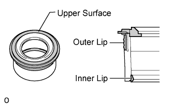
Visually check the spark plug tube gasket.
OK Inspection Area Specified Condition Upper surface No scratches or deformation Outer lip No scratches or deformation Inner lip No scratches If the result is not as specified, replace the spark plug tube gasket.
-
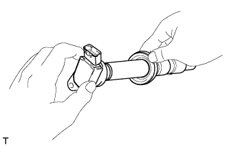
Slide the spark plug tube gasket onto the ignition coil assembly as shown in the illustration.
-
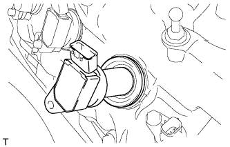
After installing the spark plug tube gasket, firmly insert the ignition coil assembly as shown in the illustration.
-
Install the 8 bolts.
- Torque:
- 10 N*m { 102 kgf*cm, 7 ft.*lbf }
-
Connect the 8 ignition coil assembly connectors.
-
-
INSTALL NO. 6 COVER SUB-ASSEMBLY
-
INSTALL ENGINE COVER SUB-ASSEMBLY LH
-
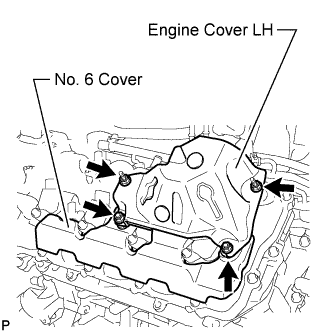
Install the engine cover LH with the 4 nuts.
- Torque:
- 21 N*m { 214 kgf*cm, 15 ft.*lbf }
-
-
INSTALL NO. 5 COVER SUB-ASSEMBLY
-
INSTALL ENGINE COVER SUB-ASSEMBLY RH
-
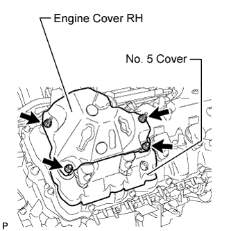
Install the engine cover RH with the 4 nuts.
- Torque:
- 21 N*m { 214 kgf*cm, 15 ft.*lbf }
-
-
INSTALL ENGINE OIL LEVEL DIPSTICK GUIDE
-
Apply a light coat of engine oil to a new O-ring.
-
Install the O-ring to the engine oil level dipstick guide.
-
Install the engine oil level dipstick guide with the bolt.
- Torque:
- 10 N*m { 102 kgf*cm, 7 ft.*lbf }
-
Install the engine oil level dipstick.
-
-
INSTALL SKID CONTROL ECU BRACKET (for RHD)
-
INSTALL SKID CONTROL ECU BRACKET (for LHD)
-
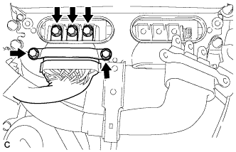
INSTALL INVERTER COOLING PIPE BRACKET (for RHD)
-
Attach the clamp of the frame wire and the clamp of the air conditioning harness to the inverter cooling pipe bracket.
-
Install the inverter cooling pipe bracket to the inverter with converter assembly with the bolt.
- Torque:
- 8.0 N*m { 82 kgf*cm, 71 in.*lbf }
-
Attach the clamp of the No. 2 inlet inverter cooling hose to the inverter cooling pipe bracket.
-
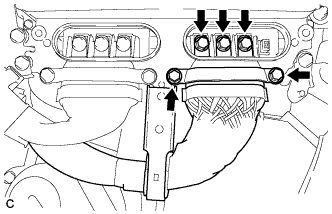
Attach the 2 clamps of the air conditioning harness to the No. 1 relay block.
-
-
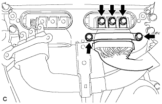
CONNECT FRAME WIRE
-
Attach the 2 claws of the frame wire to the No. 1 relay block.
-
Install the frame wire to the No. 1 relay block with the 2 nuts.
- Torque:
- 13 N*m { 130 kgf*cm, 10 ft.*lbf }
-
Install the No. 1 relay block cover.
-
-
CONNECT INLET INVERTER COOLING PIPE (for LHD)
-
Install the inlet inverter cooling pipe with the 2 bolts.
- Torque:
- 13 N*m { 127 kgf*cm, 9 ft.*lbf }
-
-
CONNECT GENERATOR CABLE (for RHD)
CAUTION:
Wear insulating gloves.
-
Connect the generator cable to the inverter with converter assembly.
-
Using an insulated tool, secure the generator cable to the inverter with converter assembly with the 5 bolts.
- Torque:
- 8.0 N*m { 82 kgf*cm, 71 in.*lbf }
Note
-
When installing the bolts that secure the cable, do not damage anything inside the inverter with converter assembly.
-
Make sure that no foreign matter is present on the terminal block.
-
Be sure to tighten the bolt to the specified torque. Failure to do so may damage the bolt.
-
-
CONNECT GENERATOR CABLE (for LHD)
CAUTION:
Wear insulating gloves.
-
Using an insulated tool, connect the generator cable to the inverter with converter assembly.
-
Secure the generator cable to the inverter with converter assembly with the 5 bolts.
- Torque:
- 8.0 N*m { 82 kgf*cm, 71 in.*lbf }
Note
-
When installing the bolts that secure the cable, do not damage anything inside the inverter with converter assembly.
-
Make sure that no foreign matter is present on the terminal block.
-
Be sure to tighten the bolt to the specified torque. Failure to do so may damage the bolt.
-
-
CONNECT MOTOR CABLE (for RHD)
CAUTION:
Wear insulating gloves.
-
Connect the motor cable to the inverter with converter assembly.
-
Using an insulated tool, secure the motor cable to the inverter with converter assembly with the 5 bolts.
- Torque:
- 8.0 N*m { 82 kgf*cm, 71 in.*lbf }
Note
-
When installing the bolts that secure the cable, do not damage anything inside the inverter with converter assembly.
-
Make sure that no foreign matter is present on the terminal block.
-
Be sure to tighten the bolt to the specified torque. Failure to do so may damage the bolt.
-
Install the motor cable bracket with the 3 bolts.
- Torque:
- 8.0 N*m { 82 kgf*cm, 71 in.*lbf }
-
-
CONNECT MOTOR CABLE (for LHD)
CAUTION:
Wear insulating gloves.
-
Using an insulated tool, connect the motor cable to the inverter with converter assembly.
-
Secure the motor cable to the inverter with converter assembly with the 5 bolts.
- Torque:
- 8.0 N*m { 82 kgf*cm, 71 in.*lbf }
Note
-
When installing the bolts that secure the cable, do not damage anything inside the inverter with converter assembly.
-
Make sure that no foreign matter is present on the terminal block.
-
Be sure to tighten the bolt to the specified torque. Failure to do so may damage the bolt
-
Install the motor cable bracket with the 3 bolts.
- Torque:
- 8.0 N*m { 82 kgf*cm, 71 in.*lbf }
-
-
INSTALL INVERTER TERMINAL COVER (for RHD)
CAUTION:
Wear insulating gloves.
-
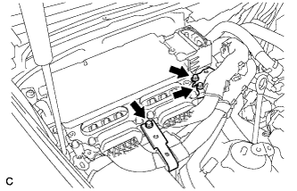
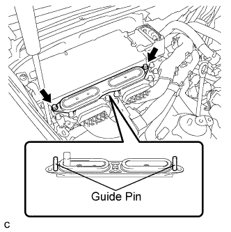
Set the inverter terminal cover to the inverter with converter assembly.
Note
-
Check that the sealing rubber is securely installed to the inverter terminal cover before installing the cover.
-
Making sure that there are no foreign objects on the waterproofed parts before installing the inverter terminal cover.
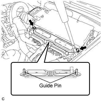
-
Install the inverter terminal cover while inserting the guide pins on both sides of the cover into guide pin holes of the inverter case.
-
When removing the inverter terminal cover, do not bend the connector terminals around the interlock part.
-
-
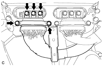
Push in both ends of the inverter terminal cover horizontally by hand.
Note
-
Insert the inverter terminal cover horizontally to prevent it from tilting. Failure to do so may damage the inverter terminal cover guide pins.
-
Make sure that both the inverter terminal cover bolt holes are aligned and in contact with the holes in the inverter case.
-
-
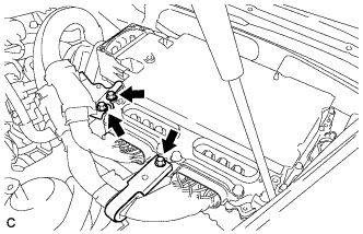
Using an insulated tool, secure the inverter terminal cover to the inverter with converter assembly with the 2 bolts.
- Torque:
- 8.0 N*m { 82 kgf*cm, 71 in.*lbf }
-
-
INSTALL INVERTER TERMINAL COVER (for LHD)
CAUTION:
Wear insulating gloves.
-
Set the inverter terminal cover to the inverter with converter assembly.
Note
-
Check that the sealing rubber is securely installed to the inverter terminal cover before installing the cover.
-
Making sure that there are no foreign objects on the waterproofed parts before installing the inverter terminal cover.
-
Install the inverter terminal cover while inserting the guide pins on both sides of the cover into guide pin holes of the inverter case.
-
When removing the inverter terminal cover, do not bend the connector terminals around the interlock part.
-
-
Push in both ends of the inverter terminal cover horizontally by hand.
Note
-
Insert the inverter terminal cover horizontally to prevent it from tilting. Failure to do so may damage the inverter terminal cover guide pins.
-
Make sure that both the inverter terminal cover bolt holes are aligned and in contact with the holes in the inverter case.
-
-
Using an insulated tool, secure the inverter terminal cover to the inverter with converter assembly with the 2 bolts.
- Torque:
- 8.0 N*m { 82 kgf*cm, 71 in.*lbf }
-
-
INSTALL INVERTER COVER ASSEMBLY LH (for RHD)
-
Install the inverter cover assembly LH and attach the 2 clips.
-
-
INSTALL INVERTER COVER ASSEMBLY RH (for LHD)
-
Install the inverter cover assembly RH and attach the 2 clips.
-
-
INSTALL MOTOR CABLE COVER LH (for RHD)
-
Install the motor cable cover LH with the 2 clips.
-
-
INSTALL MOTOR CABLE COVER RH (for LHD)
-
Install the motor cable cover RH with the 2 clips.
-
-
INSTALL COWL TOP VENTILATOR LOUVER LH (for RHD)
-
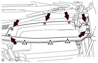
Install the hood to cowl top seal with the 4 clips.
-
Install the cowl top ventilator louver LH with the 6 clips.
-
-
INSTALL COWL TOP VENTILATOR LOUVER RH (for LHD)
-
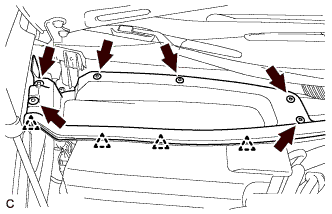
Install the hood to cowl top seal with the 4 clips.
-
Install the cowl top ventilator louver RH with the 6 clips.
-
-
INSTALL AIR CLEANER ASSEMBLY RH
-
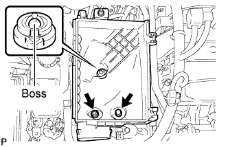
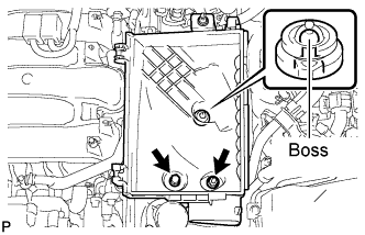
Align the air cleaner cases 2 holes to the 2 stud bolts and attach the air cleaner case RH to the boss. Then install the 2 nuts.
- Torque:
- 5.0 N*m { 51 kgf*cm, 44 in.*lbf }
-
Install the air cleaner filter element to the air cleaner case RH.
-
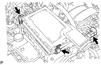
Install the air cleaner cap RH and secure the 2 clamps.
-
Connect the mass air flow meter connector.
-
-
INSTALL AIR CLEANER ASSEMBLY LH
-
Align the air cleaner cases 2 holes to the 2 stud bolts and attach the air cleaner case LH to the boss. Then install the 2 nuts.
- Torque:
- 5.0 N*m { 51 kgf*cm, 44 in.*lbf }
-
Install the air cleaner filter element to the air cleaner case LH.
-
Install the air cleaner cap LH and secure the 2 clamps.
-
Connect the mass air flow meter connector.
-
-
INSTALL INTAKE AIR CONNECTOR PIPE
-
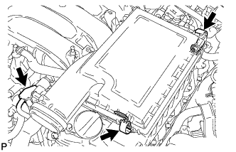
Align the protrusion of the intake air resonator with the cutout of the bracket and insert the protrusion.
-
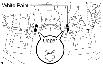
Install the intake air connector pipe with the 3 hose clamps.
- Torque:
- for intake air connector pipe and throttle body
- 4.8 N*m { 49 kgf*cm, 42 in.*lbf }
- for intake air connector pipe and intake air resonator
- 3.8 N*m { 39 kgf*cm, 34 in.*lbf }
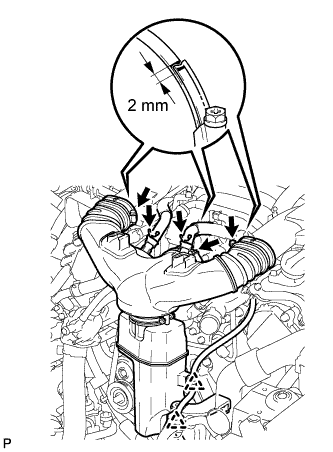
Note
Insert the protrusion of the intake air connector pipe into the hole of the hose clamp.
Tech Tips
-
The intake air connector pipe and throttle body clamp can be tightened within the range of 4.0 N*m (41 kgf*cm, 35 in.*lbf) to 5.5 N*m (56 kgf*cm, 49 in.*lbf), and the intake air connector pipe and intake air resonator clamp can be tightened within the range of 2.0 N*m (20 kgf*cm, 18 in.*lbf) to 5.5 N*m (56 kgf*cm, 49 in.*lbf).
-
When tightening the hose clamp, make sure the hose clamp's end is within the painted white line (width: 2 mm (0.0787 in.)).
-
Attach the 2 wire harness clamps.
-
Connect the No. 1 ventilation hose and No. 2 ventilation hose to the intake air connector pipe.
Tech Tips
-
Position the claws of the clamps as shown in the illustration.
-
Install the clamps so that they are within the hose's paint marks.
-
-
-
INSTALL NO. 1 AIR CLEANER INLET
-
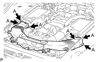
Align the holes with the connection areas labeled A, and attach the No. 1 air cleaner inlet.
-
Install the No. 1 air cleaner inlet with the 2 bolts.
- Torque:
- 5.0 N*m { 51 kgf*cm, 44 in.*lbf }
-
-
INSTALL SERVICE PLUG GRIP
-
CONNECT CABLE TO AUXILIARY BATTERY NEGATIVE TERMINAL
Note
When disconnecting the cable, some systems need to be initialized after the cable is reconnected Click here.
-
INSTALL BATTERY SERVICE HOLE COVER LH
-

Text in Illustration *A for Standard *B for Ottoman Attach the battery service hole cover LH with the clip and fastening tape.
-
-
INSTALL DECK TRIM SIDE BOARD LH (w/o Spare Tire)
-

Attach the 2 clips to install the deck trim side board LH.
-
-
INSTALL DECK BOARD ASSEMBLY (w/o Spare Tire)

-
INSTALL LUGGAGE COMPARTMENT MAT SUB-ASSEMBLY (w/ Spare Tire)

-
INSTALL ENGINE ROOM SIDE COVER LH
-
Install the engine room side cover LH with the 5 clips.
-
-
INSTALL ENGINE ROOM SIDE COVER RH
-
Install the engine room side cover RH with the 5 clips.
-
-
INSTALL AIR CLEANER INLET COVER SUB-ASSEMBLY
-
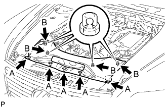
Attach the 4 clips labeled B.
Note
-
Make sure the clips are attached securely.
-
Attaching the clips forcefully or hitting the top of the clips may damage them.
-
-
Install the air cleaner inlet cover sub-assembly with the 5 clips labeled A.
-
-
INSTALL V-BANK COVER SUB-ASSEMBLY
-

After sliding the V-bank cover sub-assembly from the vehicle front to the rear to attach the 2 clips labeled A, attach the 4 clips labeled B and install the V-bank cover sub-assembly.
CAUTION:
-
Make sure the clips are attached securely.
-
Attaching the clips forcefully or hitting the top of the clips may damage them.
-
-