IGNITION COIL AND SPARK PLUG REMOVAL

Note
While the auxiliary battery is connected, even if the power switch is off, the brake control system activates when the brake pedal is depressed or the door courtesy switch turns on. Therefore during servicing of the brake system components, do not operate the brake pedal and open/close the doors while the auxiliary battery is connected.
-
REMOVE LUGGAGE COMPARTMENT MAT SUB-ASSEMBLY (w/ Spare Tire)

-
REMOVE DECK BOARD ASSEMBLY (w/o Spare Tire)

-
REMOVE DECK TRIM SIDE BOARD LH (w/o Spare Tire)
-

Detach the 2 clips and remove the deck trim side board LH.
-
-
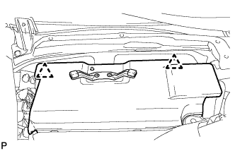
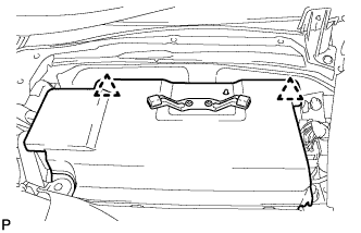
REMOVE BATTERY SERVICE HOLE COVER LH
-

Text in Illustration *A for Standard *B for Ottoman *1 Fastening Tape Detach the clip, fastening tape and remove the battery service hole cover LH.
-
-
PRECAUTION
Note
After turning the power switch off, waiting time may be required before disconnecting the cable from the auxiliary battery terminal. Therefore, make sure to read the disconnecting the cable from the auxiliary battery terminal notice before proceeding with work Click here.
-
DISCONNECT CABLE FROM AUXILIARY BATTERY NEGATIVE TERMINAL
Note
When disconnecting the cable, some systems need to be initialized after the cable is reconnected Click here.
-
REMOVE SERVICE PLUG GRIP
-
REMOVE V-BANK COVER SUB-ASSEMBLY
-

While using both hands, lift the rear side of the V-bank cover sub-assembly upwards to detach the 4 clips labeled B. Slide the V-bank cover sub-assembly towards the front of the vehicle to detach the 2 clips labeled A, and remove the V-bank cover sub-assembly.
Note
The V-bank cover sub-assembly may be damaged if its front and rear are lifted at the same time.
-
-
REMOVE AIR CLEANER INLET COVER SUB-ASSEMBLY
-
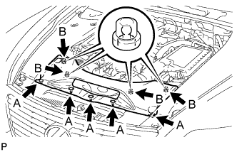
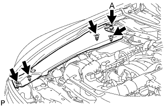
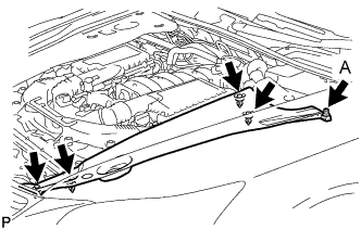
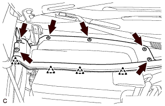
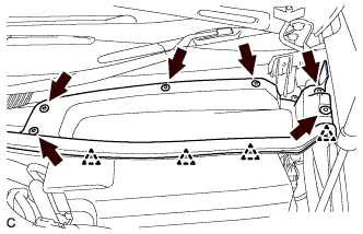
Remove the 5 clips labeled A.
-
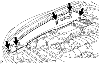
Lift up the air cleaner inlet cover sub-assembly to detach the 4 clips labeled B, and remove the air cleaner inlet cover sub-assembly.
-
-
REMOVE ENGINE ROOM SIDE COVER RH
-
for LHD:
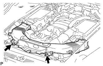
Remove the 5 clips and engine room side cover RH.
Note
Remove the clip labeled A by turning it to prevent the engine room side cover RH and bracket from being damaged.
Tech Tips
The clip labeled A cannot be removed from the engine room side cover RH.
-
for RHD:
Remove the 5 clips and engine room side cover RH.
-
-
REMOVE ENGINE ROOM SIDE COVER LH
-
for LHD:
Remove the 5 clips and engine room side cover LH.
-
for RHD:
Remove the 5 clips and engine room side cover LH.
Note
Remove the clip labeled A by turning it to prevent the engine room side cover LH and bracket from being damaged.
Tech Tips
The clip labeled A cannot be removed from the engine room side cover LH.
-
-
REMOVE NO. 1 AIR CLEANER INLET
-
Remove the 2 bolts.
-
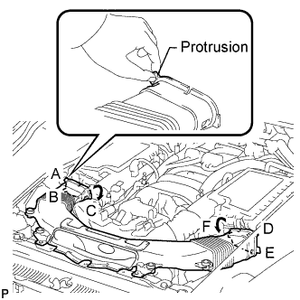
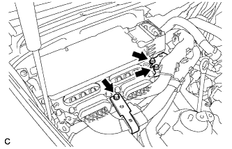
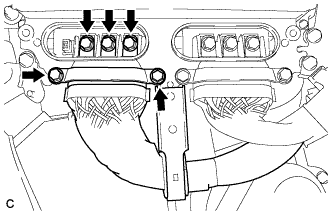
Hold the No. 1 air cleaner inlet by the protrusions labeled A and B, and detach the connections.
-
Rotate the No. 1 air cleaner inlet as shown in the illustration to detach the protrusion labeled C.
-
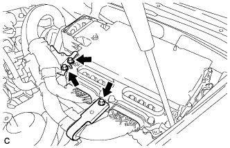
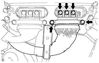
Hold the No. 1 air cleaner inlet by the protrusions labeled D and E, and detach the connections.
-
Rotate the No. 1 air cleaner inlet as shown in the illustration to detach the protrusion labeled F.
-
-
REMOVE INTAKE AIR CONNECTOR PIPE
-
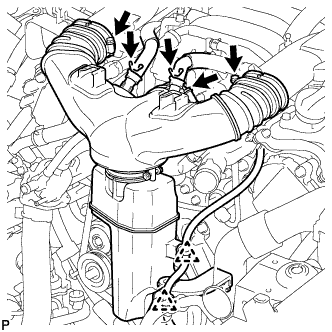
Disconnect the No. 1 ventilation hose and No. 2 ventilation hose from the intake air connector pipe.
-
Using a clip remover, detach the 2 wire harness clamps.
-
Loosen the 3 hose clamps, and remove the intake air connector pipe.
-
-
REMOVE AIR CLEANER ASSEMBLY LH
-
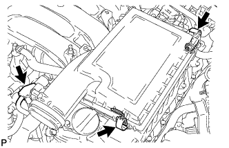
Disconnect the mass air flow meter connector.
-
Release the 2 clamps and remove the air cleaner cap LH.
-
Remove the air cleaner filter element from the air cleaner case LH.
-
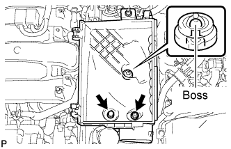
Remove the 2 nuts and detach the air cleaner case LH from the boss.
-
-
REMOVE AIR CLEANER ASSEMBLY RH
-
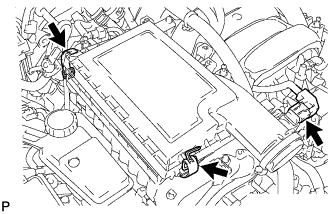
Disconnect the mass air flow meter connector.
-
Release the 2 clamps and remove the air cleaner cap RH.
-
Remove the air cleaner filter element from the air cleaner case RH.
-
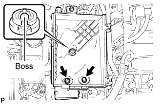
Remove the 2 nuts and detach the air cleaner case RH from the boss.
-
-
REMOVE COWL TOP VENTILATOR LOUVER RH (for LHD)
-
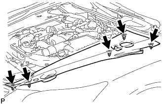
Remove the 4 clips and hood to cowl top seal.
-
Remove the 6 clips and cowl top ventilator louver RH.
-
-
REMOVE COWL TOP VENTILATOR LOUVER LH (for RHD)
-
Remove the 4 clips and hood to cowl top seal.
-
Remove the 6 clips and cowl top ventilator louver LH.
-
-
REMOVE MOTOR CABLE COVER RH (for LHD)
-
Remove the 2 clips and motor cable cover RH.
-
-
REMOVE MOTOR CABLE COVER LH (for RHD)
-
Remove the 2 clips and motor cable cover LH.
-
-
REMOVE INVERTER COVER ASSEMBLY RH (for LHD)
-
Detach the 2 clips and remove the inverter cover assembly RH.
-
-
REMOVE INVERTER COVER ASSEMBLY LH (for RHD)
-
Detach the 2 clips and remove the inverter cover assembly LH.
-
-
REMOVE CONNECTOR COVER ASSEMBLY (for LHD)
CAUTION:
Wear insulating gloves.
-
Using an insulated tool, remove the 2 bolts and connector cover assembly.
Note
-
Cover the hole where the cable was connected with tape or equivalent (non-residue type) to prevent entry of foreign matter.
-
Do not touch the high voltage connectors or terminals for 10 minutes after the service plug grip is removed.
-
-
-
REMOVE CONNECTOR COVER ASSEMBLY (for RHD)
CAUTION:
Wear insulating gloves.
-
Using an insulated tool, remove the 2 bolts and connector cover assembly.
Note
-
Cover the hole where the cable was connected with tape or equivalent (non-residue type) to prevent entry of foreign matter.
-
Do not touch the high voltage connectors or terminals for 10 minutes after the service plug grip is removed.
-
-
-
CHECK TERMINAL VOLTAGE (for LHD)
CAUTION:
Wear insulating gloves.
-
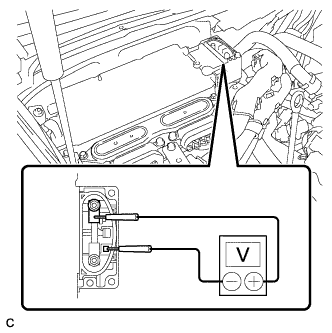
Using the voltmeter, measure the voltage between the terminals of the 2 phase connectors.
Standard voltage 0 V Tech Tips
Use measuring range of DC 750 V or more on the voltmeter.
-
-
CHECK TERMINAL VOLTAGE (for RHD)
CAUTION:
Wear insulating gloves.
-
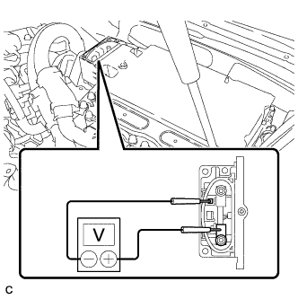
Using the voltmeter, measure the voltage between the terminals of the 2 phase connectors.
Standard voltage 0 V Tech Tips
Use measuring range of DC 750 V or more on the voltmeter.
-
-
INSTALL CONNECTOR COVER ASSEMBLY (for LHD)
CAUTION:
Wear insulating gloves.
-
Using an insulated tool, install the connector cover assembly with the 2 bolts.
- Torque:
- 8.0 N*m { 82 kgf*cm, 71 in.*lbf }
-
-
INSTALL CONNECTOR COVER ASSEMBLY (for RHD)
CAUTION:
Wear insulating gloves.
-
Using an insulated tool, install the connector cover assembly with the 2 bolts.
- Torque:
- 8.0 N*m { 82 kgf*cm, 71 in.*lbf }
-
-
REMOVE INVERTER TERMINAL COVER (for LHD)
CAUTION:
Wear insulating gloves.
Note
Lift the inverter terminal cover horizontally so that it will not tilt. Failure to do so may break the inverter cover guide pins.
-
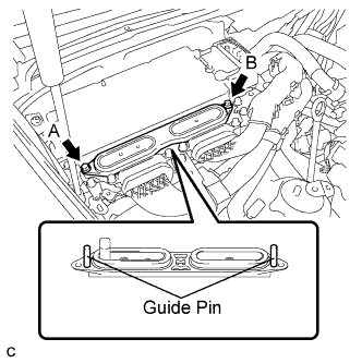
Using an insulated tool, remove the 2 bolts.
-
Insert and gradually rotate a screwdriver between the inverter terminal cover and inverter case near bolt hole A to raise the terminal cover by approximately 2 mm (0.08 in.). (*1)
Note
Tape the screwdriver tip before use.
-
Insert and gradually rotate a screwdriver between the inverter terminal cover and inverter case near bolt hole B to raise the terminal cover by approximately 2 mm (0.08 in.). (*2)
Note
Tape the screwdriver tip before use.
Tech Tips
Repeat the preceding steps (*1) and (*2) until the inverter cover can be easily removed by hand.
-
Remove the inverter terminal cover by hand.
Note
-
Do not allow any foreign objects to enter the waterproofed parts of the removed inverter terminal cover.
-
Do not touch the waterproofed parts.
-
When removing the inverter terminal cover, do not bend the connector terminals around the interlock part.
-
Cover the hole where the cable was connected with tape or equivalent (non-residue type) to prevent entry of foreign matter.
-
-
-
REMOVE INVERTER TERMINAL COVER (for RHD)
CAUTION:
Wear insulating gloves.
Note
Lift the inverter terminal cover horizontally so that it will not tilt. Failure to do so may break the inverter cover guide pins.
-
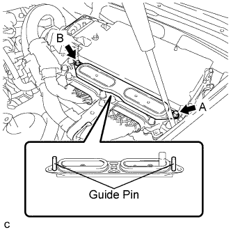
Using an insulated tool, remove the 2 bolts.
-
Insert and gradually rotate a screwdriver between the inverter terminal cover and inverter case near bolt hole A to raise the terminal cover by approximately 2 mm (0.08 in.). (*1)
Note
Tape the screwdriver tip before use.
-
Insert and gradually rotate a screwdriver between the inverter terminal cover and inverter case near bolt hole B to raise the terminal cover by approximately 2 mm (0.08 in.). (*2)
Note
Tape the screwdriver tip before use.
Tech Tips
Repeat the preceding steps (*1) and (*2) until the inverter cover can be easily removed by hand.
-
Remove the inverter terminal cover by hand.
Note
-
Do not allow any foreign objects to enter the waterproofed parts of the removed inverter terminal cover.
-
Do not touch the waterproofed parts.
-
When removing the inverter terminal cover, do not bend the connector terminals around the interlock part.
-
Cover the hole where the cable was connected with tape or equivalent (non-residue type) to prevent entry of foreign matter.
-
-
-
DISCONNECT MOTOR CABLE (for LHD)
CAUTION:
Wear insulating gloves.
-
Remove the 3 bolts and separate the motor cable bracket.
-
Using an insulated tool, remove the 5 bolts and pull out the motor cable from the inverter with converter assembly.
Note
-
Cover the hole where the cable was connected with tape or equivalent (non-residue type) to prevent entry of foreign matter.
-
When removing the bolts that secure the cable, do not damage anything inside the inverter with converter assembly.
-
-
-
DISCONNECT MOTOR CABLE (for RHD)
CAUTION:
Wear insulating gloves.
-
Remove the 3 bolts and separate the motor cable bracket.
-
Using an insulated tool, remove the 5 bolts and pull out the motor cable from the inverter with converter assembly.
Note
-
Cover the hole where the cable was connected with tape or equivalent (non-residue type) to prevent entry of foreign matter.
-
When removing the bolts that secure the cable, do not damage anything inside the inverter with converter assembly.
-
-
-
DISCONNECT GENERATOR CABLE (for LHD)
CAUTION:
Wear insulating gloves.
-
Using an insulated tool, remove the 5 bolts and pull out the generator cable from the inverter with converter assembly.
Note
-
Cover the hole where the cable was connected with tape or equivalent (non-residue type) to prevent entry of foreign matter.
-
When removing the bolts that secure the cable, do not damage anything inside the inverter with converter assembly.
-
-
-
DISCONNECT GENERATOR CABLE (for RHD)
CAUTION:
Wear insulating gloves.
-
Using an insulated tool, remove the 5 bolts and pull out the generator cable from the inverter with converter assembly.
Note
-
Cover the hole where the cable was connected with tape or equivalent (non-residue type) to prevent entry of foreign matter.
-
When removing the bolts that secure the cable, do not damage anything inside the inverter with converter assembly.
-
-
-
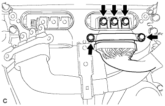
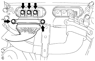
DISCONNECT INLET INVERTER COOLING PIPE (for LHD)
-
Remove the 2 bolts and disconnect the inlet inverter cooling pipe.
-
-
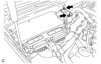
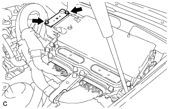
DISCONNECT FRAME WIRE
-
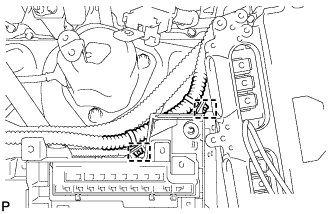
Remove the No. 1 relay block cover.
-
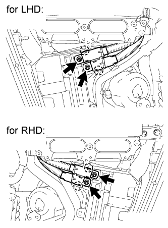
Remove the 2 nuts from the No. 1 relay block.
-
Detach the 2 claws to disconnect the frame wire from the No. 1 relay block.
-
-
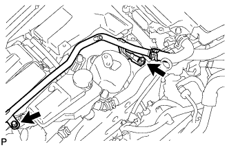
REMOVE INVERTER COOLING PIPE BRACKET (for RHD)
-
Detach the 2 clamps to disconnect the air conditioning harness from the No. 1 relay block.
-
Detach the clamp of the No. 2 inlet inverter cooling hose from the inverter cooling pipe bracket.
-
Remove the bolt, and then remove the inverter cooling pipe bracket from the inverter with converter assembly.
-
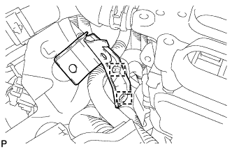
Detach the clamp of the frame wire and the clamp of the air conditioning harness. Then remove the inverter cooling pipe bracket.
-
-
REMOVE SKID CONTROL ECU BRACKET (for LHD)
-
REMOVE SKID CONTROL ECU BRACKET (for RHD)
-
REMOVE ENGINE OIL LEVEL DIPSTICK GUIDE
-
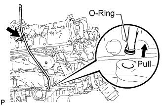
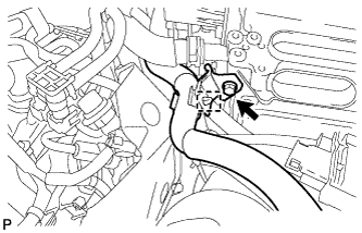
Remove the engine oil level dipstick.
-
Remove the bolt and engine oil level dipstick guide.
-
Remove the O-ring from the engine oil level dipstick guide.
-
-
REMOVE ENGINE COVER SUB-ASSEMBLY RH
-
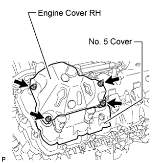
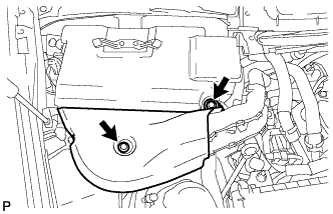
Remove the 4 nuts and engine cover RH.
-
-
REMOVE NO. 5 COVER SUB-ASSEMBLY
-
REMOVE ENGINE COVER SUB-ASSEMBLY LH
-
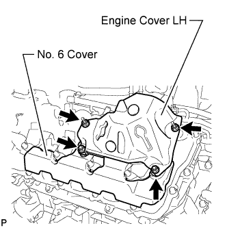
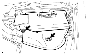
Remove the 4 nuts and engine cover LH.
-
-
REMOVE NO. 6 COVER SUB-ASSEMBLY
-
REMOVE IGNITION COIL ASSEMBLY
-
Disconnect the 8 ignition coil assembly connectors.
-
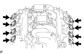
Remove the 8 bolts.
-
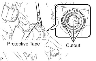
Using a screwdriver, pry at the cutouts to remove the 8 ignition coil assemblies together with the 8 spark plug tube gaskets.
Note
Do not damage the cylinder head cover when removing the spark plug tube gasket.
Tech Tips
Tape the screwdriver tip before use.
-
-
REMOVE SPARK PLUG
-
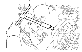
Using a 16 mm plug wrench, remove the 8 spark plugs.
-