INTAKE MANIFOLD INSTALLATION

-
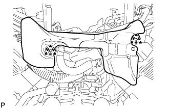
INSTALL INTAKE MANIFOLD
-
Install 2 new gaskets to the intake manifold.
-
Temporarily Install the intake manifold with the 8 bolts and 2 nuts.
-
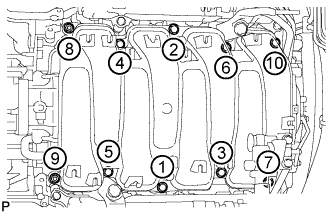
Uniformly tighten the bolts and nuts in the order shown in the illustration.
- Torque:
- 21 N*m { 214 kgf*cm, 15 ft.*lbf }
-
-
CONNECT PCV HOSE
-
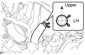
Connect the PCV hose to the intake manifold.
Tech Tips
Make sure the direction of the hose clamp is as shown in the illustration.
-
-
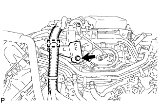
INSTALL PURGE VSV
-
Install the purge VSV with the bolt.
- Torque:
- 21 N*m { 214 kgf*cm, 15 ft.*lbf }
-
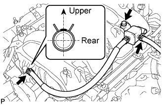
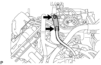
Connect the 2 purge line hoses.
Tech Tips
Make sure the direction of the hose clamp is as shown in the illustration.
-
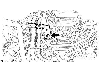
Connect the purge VSV connector.
-
-
INSTALL WATER BY-PASS PIPE HOSE
-
Install the water by-pass pipe hose with the 2 bolts.
- Torque:
- 10 N*m { 102 kgf*cm, 7 ft.*lbf }
-
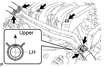
Connect the 4 water hoses.
Tech Tips
Make sure the direction of the hose clamp is as shown in the illustration.
-
-
INSTALL NO. 3 ENGINE COVER SUB-ASSEMBLY
-
Install the No. 3 cover sub-assembly with the 2 clips.
-
-
INSTALL ENGINE MOTOR CABLE CLAMP BRACKET (for LHD)
-
Install the engine motor cable clamp bracket with the bolt.
- Torque:
- 10 N*m { 102 kgf*cm, 7 ft.*lbf }
-
Connect the wire harness clamp to the motor cable clamp bracket.
-
-
INSTALL FLEXIBLE HOSE BRACKET SUB-ASSEMBLY (for LHD)
-
Install the flexible hose bracket sub-assembly with the bolt.
- Torque:
- 8.0 N*m { 82 kgf*cm, 71 in.*lbf }
-
Connect the flexible hose to the bracket.
-
-
INSTALL NO. 2 ENGINE MOTOR CABLE CLAMP BRACKET (for RHD)
-
Install the No. 2 engine motor cable bracket with the bolt.
- Torque:
- 10 N*m { 102 kgf*cm, 7 ft.*lbf }
-
Attach the 2 wire harness clamps to the bracket.
-
-
INSTALL NO. 1 ENGINE MOTOR CABLE CLAMP BRACKET (for RHD)
-
Install the No. 1 engine motor cable clamp bracket with the bolt to the No. 2 engine motor cable bracket.
- Torque:
- 8.0 N*m { 82 kgf*cm, 71 in.*lbf }
-
-
CONNECT GENERATOR CABLE (for RHD)
-
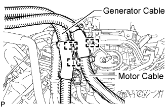
Connect the generator cable with the 2 clamps.
-
-
CONNECT MOTOR CABLE (for RHD)
-
Connect the motor cable with the clamp.
-
-
INSTALL INJECTOR DRIVER
-
Install the No. 1 engine cover to the intake manifold.
-
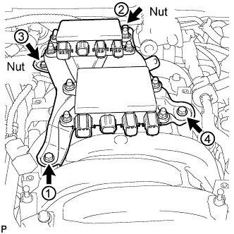
Install the injector driver with the 2 bolts and 2 nuts.
-
Uniformly tighten the bolts and nuts in the order shown in the illustration.
- Torque:
- 10 N*m { 102 kgf*cm, 7 ft.*lbf }
-
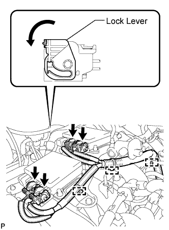
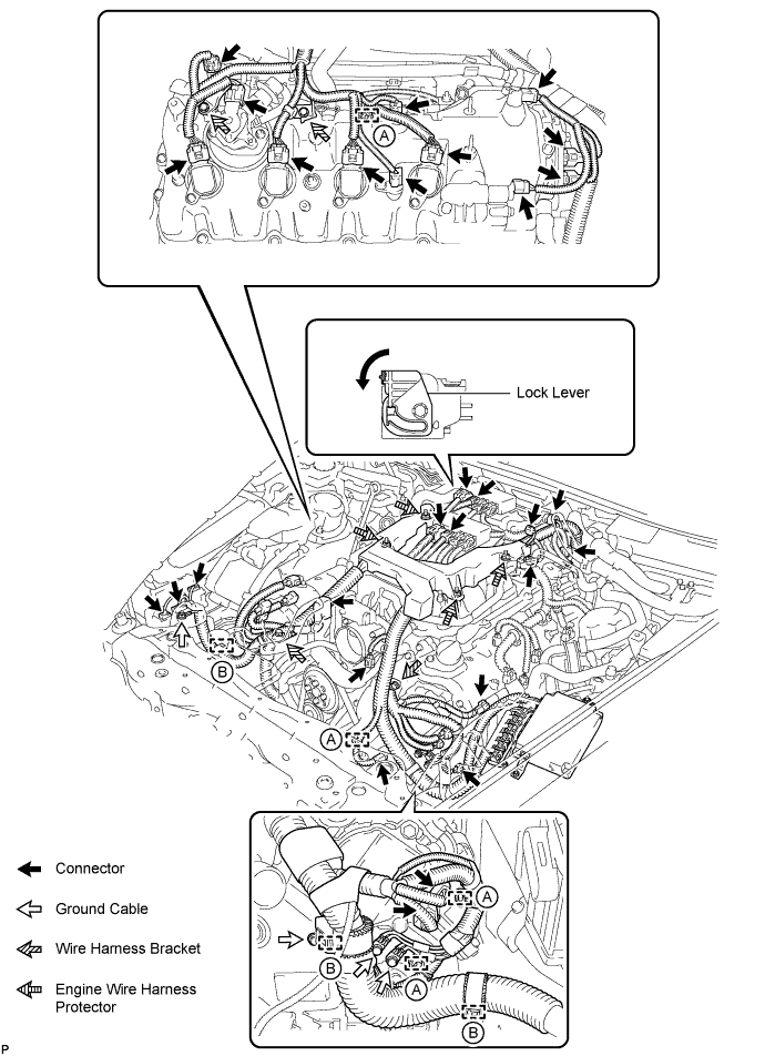
Connect the 4 wire harness connectors to the injector driver. Then move the lock lever as shown in the illustration to lock the connectors.
-
Connect the 3 wire harness claws to the bracket.
-
-
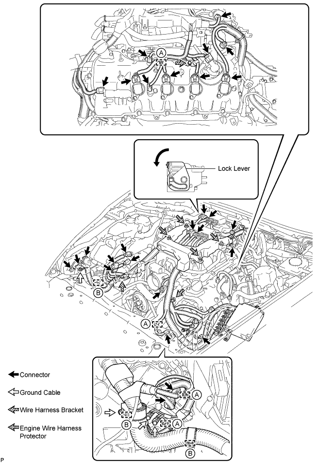
CONNECT ENGINE WIRE HARNESS (for LHD)
-
Connect the engine wire harness protector to the intake manifold with the 4 nuts.
- Torque:
- 10 N*m { 102 kgf*cm, 7 ft.*lbf }
-
Connect the 3 wire harness brackets with the 3 bolts.
- Torque:
- 10 N*m { 102 kgf*cm, 7 ft.*lbf }
-
Connect the 4 ground cables with the 4 bolts.
- Torque:
- for timing chain cover
- 10 N*m { 102 kgf*cm, 7 ft.*lbf }
- for engine room RH side
- 8.5 N*m { 87 kgf*cm, 75 in.*lbf }
-
Connect the 3 engine wire harness clamps labeled B.
-
Attach the 4 engine wire harness clamps labeled A.
-
Connect the engine wire harness connectors.
Tech Tips
Connect the 4 wire harness connectors to the injector driver. Then move the lock lever as shown in the illustration to lock the connectors.
-
-
CONNECT ENGINE WIRE HARNESS (for RHD)
-
Connect the engine wire harness protector to the intake manifold with the 4 nuts.
- Torque:
- 10 N*m { 102 kgf*cm, 7 ft.*lbf }
-
Connect the 4 wire harness brackets with the 4 bolts.
- Torque:
- 10 N*m { 102 kgf*cm, 7 ft.*lbf }
-
Connect the 4 ground cables with the 4 bolts.
- Torque:
- for timing chain cover
- 10 N*m { 102 kgf*cm, 7 ft.*lbf }
- for engine room RH side
- 8.5 N*m { 87 kgf*cm, 75 in.*lbf }
-
Connect the 3 engine wire harness clamps labeled B.
-
Attach the 4 engine wire harness clamps labeled A.
-
Connect the engine wire harness connectors.
Tech Tips
Connect the 4 wire harness connectors to the injector driver. Then move the lock lever as shown in the illustration to lock the connectors.
-
-
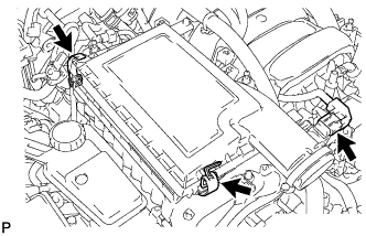
CONNECT ECM CONNECTOR
-
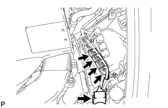
Connect the engine wire harness to the ECM box and connect the 4 ECM connectors.
-
-
CONNECT NO. 2 CONNECTOR HOLDER
-
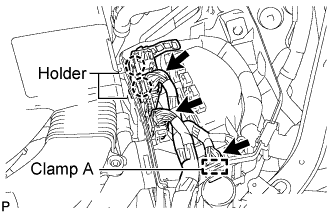
Attach the No. 2 connector holder.
-
Attach the wire harness clamp A to the ECM box.
-
Connect the 3 connectors.
-
-
CONNECT HYBRID VEHICLE CONTROL ECU CONNECTOR
-
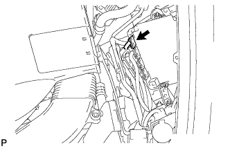
Connect the connector to the hybrid vehicle control ECU.
-
-
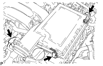
INSTALL OUTLET ENGINE ROOM ECM DUCT
-
Install the outlet engine room ECM duct.
-
-
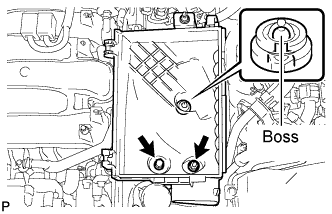
INSTALL ENGINE ROOM ECU COVER
-
Install the engine room ECU cover with the 3 bolts.
- Torque:
- 5.5 N*m { 56 kgf*cm, 49 in.*lbf }
-
-
INSTALL NO. 6 COVER SUB-ASSEMBLY (for LHD)
-
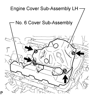
Install the No. 6 cover sub-assembly.
-
-
INSTALL ENGINE COVER SUB-ASSEMBLY LH (for LHD)
-
Install the engine cover sub-assembly LH with the 4 nuts.
- Torque:
- 21 N*m { 214 kgf*cm, 15 ft.*lbf }
-
-
INSTALL NO. 5 COVER SUB-ASSEMBLY (for RHD)
-
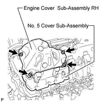
Install the No. 5 cover sub-assembly.
-
-
INSTALL ENGINE COVER SUB-ASSEMBLY RH (for RHD)
-
Install the engine cover sub-assembly RH with the 4 nuts.
- Torque:
- 21 N*m { 214 kgf*cm, 15 ft.*lbf }
-
-
INSTALL ENGINE OIL LEVEL DIPSTICK GUIDE (for RHD)
-
Apply a light coat of engine oil to a new O-ring.
-
Install the O-ring to the engine oil level dipstick guide.
-
Install the engine oil level dipstick guide with the bolt.
- Torque:
- 10 N*m { 102 kgf*cm, 7 ft.*lbf }
-
Install the engine oil level dipstick.
-
-
INSTALL ENGINE OIL LEVEL DIPSTICK (for RHD)
-
INSTALL SKID CONTROL ECU BRACKET (for LHD)
-
INSTALL SKID CONTROL ECU BRACKET (for RHD)
-
INSTALL AIR CLEANER ASSEMBLY RH
-
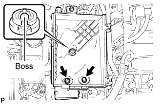
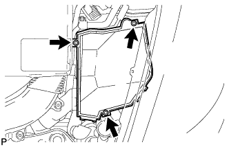
Align the air cleaner cases 2 holes to the 2 stud bolts and attach the air cleaner case RH to the boss. Then install the 2 nuts.
- Torque:
- 5.0 N*m { 51 kgf*cm, 44 in.*lbf }
-
Install the air cleaner filter element to the air cleaner case RH.
-
Install the air cleaner cap RH and secure the 2 clamps.
-
Connect the mass air flow meter connector.
-
-
INSTALL AIR CLEANER ASSEMBLY LH
-
Align the air cleaner cases 2 holes to the 2 stud bolts and attach the air cleaner case LH to the boss. Then install the 2 nuts.
- Torque:
- 5.0 N*m { 51 kgf*cm, 44 in.*lbf }
-
Install the air cleaner filter element to the air cleaner case LH.
-
Install the air cleaner cap LH and secure the 2 clamps.
-
Connect the mass air flow meter connector.
-
-
INSTALL THROTTLE BODY ASSEMBLY
-
INSTALL SERVICE PLUG GRIP
-
CONNECT CABLE TO AUXILIARY BATTERY NEGATIVE TERMINAL
Note
When disconnecting the cable, some systems need to be initialized after the cable is reconnected Click here.
-
INSTALL DECK TRIM SIDE BOARD LH (w/o Spare Tire)
-

Attach the 2 clips to install the deck trim side board LH.
-
-
INSTALL LUGGAGE COMPARTMENT MAT SUB-ASSEMBLY

-
INSTALL ENGINE ROOM SIDE COVER LH
-
Install the engine room side cover LH with the 5 clips.
-
-
INSTALL ENGINE ROOM SIDE COVER RH
-
Install the engine room side cover RH with the 5 clips.
-