INTAKE MANIFOLD REMOVAL

-
PRECAUTION
CAUTION:
Be sure to read Precaution thoroughly before servicing Click here.
Note
After turning the power switch off, waiting time may be required before disconnecting the cable from the auxiliary battery terminal. Therefore, make sure to read the disconnecting the cable from the auxiliary battery terminal notice before proceeding with work Click here.
-
REMOVE LUGGAGE COMPARTMENT MAT SUB-ASSEMBLY (w/ Spare Tire)

-
REMOVE DECK BOARD ASSEMBLY (w/o Spare Tire)
-
REMOVE DECK TRIM SIDE BOARD LH (w/o Spare Tire)
-

Detach the 2 clips and remove the deck trim side board LH.
-
-
REMOVE BATTERY SERVICE HOLE COVER LH
-

Text in Illustration *A for Standard *B for Ottoman *1 Fastening Tape Detach the clip, fastening tape and remove the battery service hole cover LH.
-
-
DISCONNECT CABLE FROM AUXILIARY BATTERY NEGATIVE TERMINAL
CAUTION:
Wait at least 90 seconds after disconnecting the cable from the auxiliary negative (-) battery terminal to prevent airbag and seat belt pretensioner activation.
Note
When disconnecting the cable, some systems need to be initialized after the cable is reconnected Click here.
-
REMOVE SERVICE PLUG GRIP
-
REMOVE ENGINE ROOM SIDE COVER RH
-
for LHD:
Remove the 5 clips and engine room side cover RH.
Note
Remove the clip labeled A by turning it to prevent the engine room side cover RH and bracket from being damaged.
Tech Tips
The clip labeled A cannot be removed from the engine room side cover RH.
-
for RHD:
Remove the 5 clips and engine room side cover RH.
-
-
REMOVE ENGINE ROOM SIDE COVER LH
-
for LHD:
Remove the 5 clips and engine room side cover LH.
-
for RHD:
Remove the 5 clips and engine room side cover LH.
Note
Remove the clip labeled A by turning it to prevent the engine room side cover LH and bracket from being damaged.
Tech Tips
The clip labeled A cannot be removed from the engine room side cover LH.
-
-
REMOVE THROTTLE BODY ASSEMBLY
-
REMOVE AIR CLEANER ASSEMBLY LH
-
Disconnect the mass air flow meter connector.
-
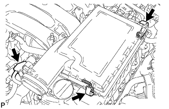
Release the 2 clamps and remove the air cleaner cap LH.
-
Remove the air cleaner filter element from the air cleaner case LH.
-
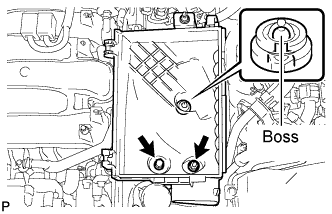
Remove the 2 nuts and detach the air cleaner case LH from the boss.
-
-
REMOVE AIR CLEANER ASSEMBLY RH
-
Disconnect the mass air flow meter connector.
-
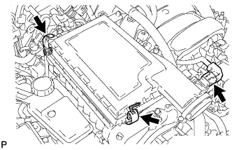
Release the 2 clamps and remove the air cleaner cap RH.
-
Remove the air cleaner filter element from the air cleaner case RH.
-
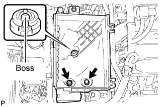
Remove the 2 nuts and detach the air cleaner case RH from the boss.
-
-
REMOVE SKID CONTROL ECU BRACKET (for LHD)
-
REMOVE SKID CONTROL ECU BRACKET (for RHD)
-
REMOVE ENGINE COVER SUB-ASSEMBLY LH (for LHD)
-
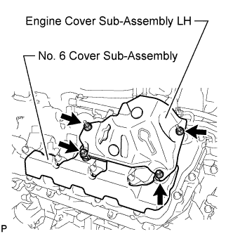
Remove the 4 nuts and engine cover sub-assembly LH.
-
-
REMOVE NO. 6 COVER SUB-ASSEMBLY (for LHD)
-
Remove the No. 6 cover sub-assembly.
-
-
REMOVE ENGINE OIL LEVEL DIPSTICK (for RHD)
-
REMOVE ENGINE OIL LEVEL DIPSTICK GUIDE (for RHD)
-
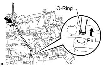
Remove the engine oil level dipstick.
-
Remove the bolt and engine oil level dipstick guide.
-
Remove the O-ring from the engine oil level dipstick guide.
-
-
REMOVE ENGINE COVER SUB-ASSEMBLY RH (for RHD)
-
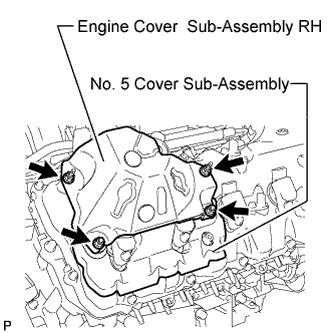
Remove the 4 nuts and engine cover sub-assembly RH.
-
-
REMOVE NO. 5 COVER SUB-ASSEMBLY (for RHD)
-
Remove the No. 5 cover sub-assembly.
-
-
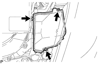
REMOVE ENGINE ROOM ECU COVER
Note
-
Wipe off any water on or around the ECU cover.
-
Perform these procedures in a dry place away from rain, etc.
-
Do not allow water to enter the ECM through its connectors areas, screw areas, etc.
-
Remove the 3 bolts and engine room ECU cover.
-
-
REMOVE OUTLET ENGINE ROOM ECM DUCT
-
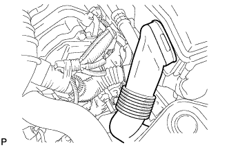
Remove the outlet engine room ECM duct.
-
-
DISCONNECT HYBRID VEHICLE CONTROL ECU CONNECTOR
-
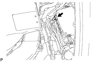
Disconnect the connector from the hybrid vehicle control ECU.
-
-
DISCONNECT NO. 2 CONNECTOR HOLDER
-
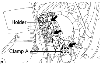
Disconnect the 3 connectors.
-
Detach the wire harness clamp A from the ECM box.
-
Detach the 2 claws and remove the No. 2 connector holder.
-
-
DISCONNECT ECM CONNECTOR
-
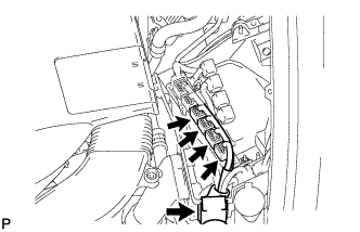
Disconnect the 4 ECM connectors and remove the engine wire harness from the ECM box.
-
-
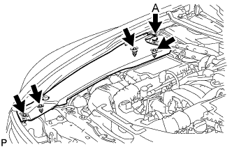
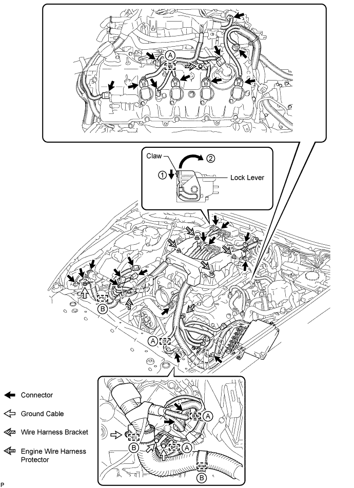
DISCONNECT ENGINE WIRE HARNESS (for LHD)
-
Disconnect the engine wire harness connectors.
Tech Tips
To disconnect the 4 injector driver connectors, (1) push the claw downward and (2) move the lock lever to release the lock.
-
Using a clip remover, detach the 4 engine wire harness clamps labeled A.
-
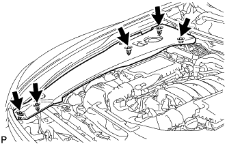
Disconnect the 3 engine wire harness clamps labeled B.
-
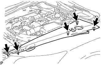
Remove the 4 bolts and disconnect the 4 ground cables.
-
Remove the 3 bolts and disconnect the 3 wire harness brackets.
-
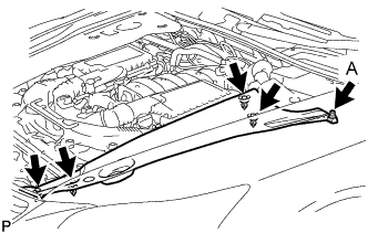
Remove the 4 nuts and disconnect the engine wire harness protector from the intake manifold.
-
-
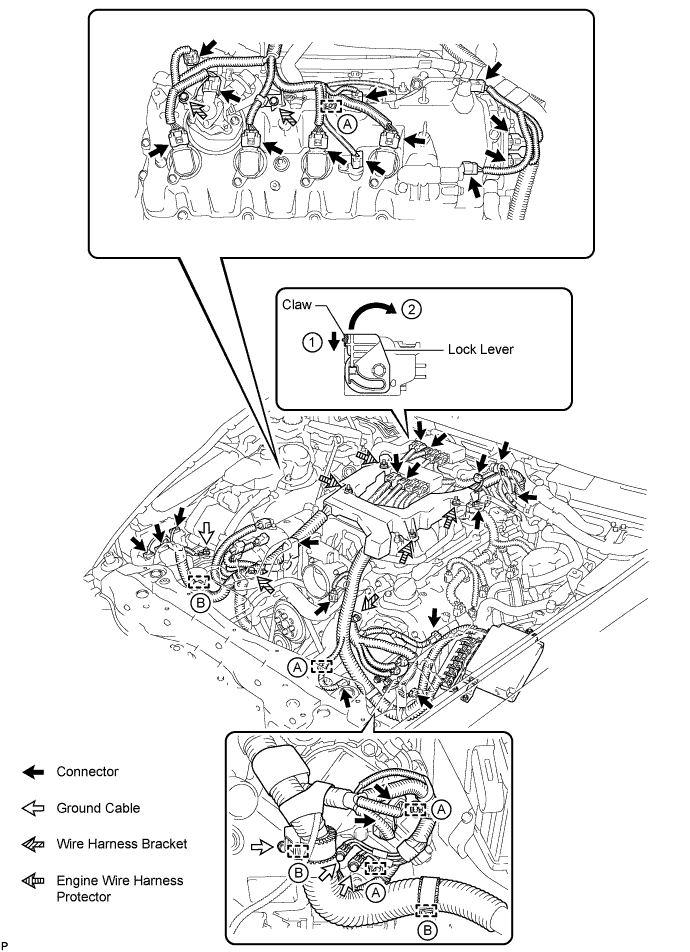
DISCONNECT ENGINE WIRE HARNESS (for RHD)
-
Disconnect the engine wire harness connectors.
Tech Tips
To disconnect the 4 injector driver connectors, (1) push the claw downward and (2) move the lock lever to release the lock.
-
Using a clip remover, detach the 4 engine wire harness clamps labeled A.
-
Disconnect the 3 engine wire harness clamps labeled B.
-
Remove the 4 bolts and disconnect the 4 ground cables.
-
Remove the 4 bolts and disconnect the 4 wire harness brackets.
-
Remove the 4 nuts and disconnect the engine wire harness protector from the intake manifold.
-
-
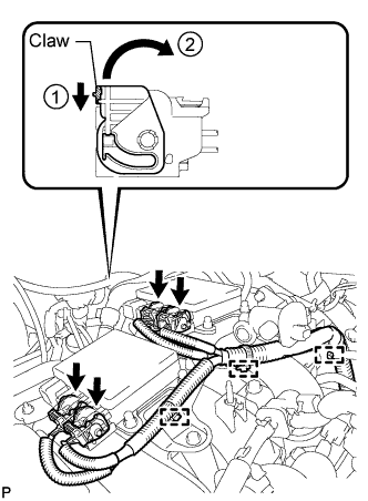
REMOVE INJECTOR DRIVER
-
Disconnect the 4 injector driver connectors as follows: (1) push the claw downward, and (2) move the lock lever to release the lock.
-
Using a clip remover, detach the 3 clamps.
-
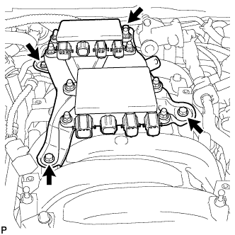
Remove the 2 bolts, 2 nuts and injector driver.
-
Remove the No. 1 engine cover.
-
-
REMOVE FLEXIBLE HOSE BRACKET SUB-ASSEMBLY (for LHD)
-
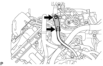
Disconnect the flexible hose.
-
Remove the bolt and flexible hose bracket sub-assembly.
-
-
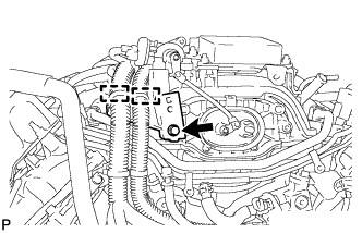
REMOVE ENGINE MOTOR CABLE CLAMP BRACKET (for LHD)
-
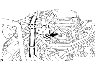
Using a clip remover, detach the wire harness clamp.
-
Remove the bolt and engine motor cable clamp bracket.
-
-
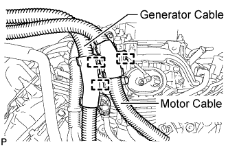
DISCONNECT MOTOR CABLE (for RHD)
-
Detach the clamp and disconnect the motor cable.
-
-
DISCONNECT GENERATOR CABLE (for RHD)
-
Detach the 2 clamps and disconnect the generator cable.
-
-
REMOVE NO. 1 ENGINE MOTOR CABLE CLAMP BRACKET (for RHD)
-
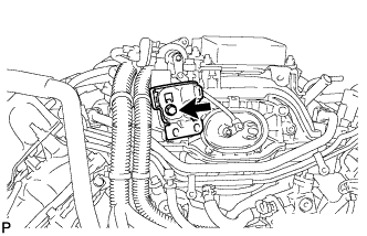
Remove the bolt and No. 1 motor cable clamp bracket.
-
-
REMOVE NO. 2 ENGINE MOTOR CABLE CLAMP BRACKET (for RHD)
-
Using a clip remover, detach the 2 wire harness clamps.
-
Remove the bolt and No. 2 engine motor cable clamp bracket.
-
-
REMOVE NO. 3 ENGINE COVER SUB-ASSEMBLY
-
Remove the 2 clips and No. 3 cover sub-assembly.
-
-
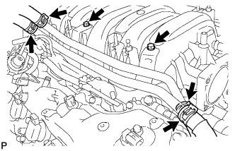
REMOVE WATER BY-PASS PIPE HOSE
-
Disconnect the 4 water hoses and remove the 2 bolts and water by-pass pipe hose.
-
-
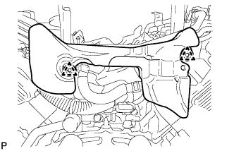
REMOVE PURGE VSV
-
Disconnect the purge VSV connector.
-
Disconnect the 2 purge line hoses.
-
Remove the bolt and purge VSV.
-
-
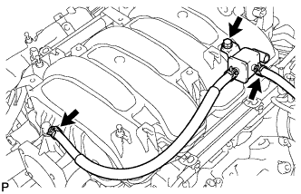
DISCONNECT PCV HOSE
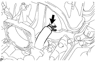
-
Disconnect the PCV hose from the intake manifold.
-
-
REMOVE INTAKE MANIFOLD
-
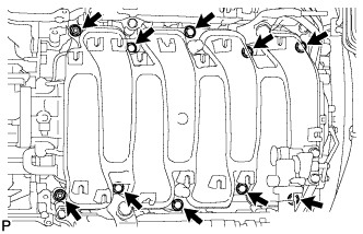
Remove the 8 bolts, 2 nuts and intake manifold.
-
Remove the 2 gaskets.
-