FUEL TANK INSTALLATION

-
INSTALL NO. 1 FUEL TANK PROTECTOR SUB-ASSEMBLY
-
Install the fuel tank protector to the fuel tank.
-
-
INSTALL FUEL TANK MAIN TUBE SUB-ASSEMBLY
-
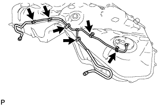
Install the fuel tube 6 clamps.
-
Install the fuel tank main tube to the fuel tank with the 6 clamps.
-
-
INSTALL FUEL TANK RETURN VENT TUBE
-
Install the fuel tank return vent tube to the fuel tank.
-
-
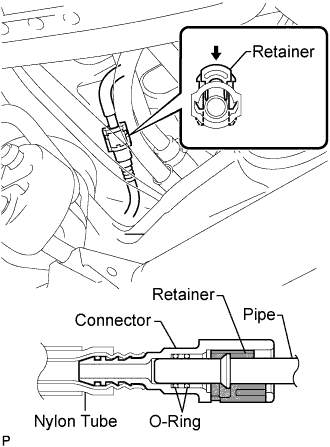
INSTALL FUEL TANK TO CANISTER TUBE SUB-ASSEMBLY
-
Install the canister tube to the fuel tank.
Note
-
Before installing the tube connectors to the pipes, check if there is any damage or foreign matter in the connectors.
-
After the connection, check if the connectors and pipes are securely connected by trying to pull them apart.
Tech Tips
Push the parts together firmly until a "click" sound is heard.
-
-
-
INSTALL NO. 1 FUEL TANK BREATHER TUBE SUB-ASSEMBLY
-
Install new gasket and the breather tube with the 4 screws.
- Torque:
- 1.5 N*m { 15 kgf*cm, 13 in.*lbf }
-
-
INSTALL FUEL TANK ASSEMBLY
-
Set the fuel tank on a engine lifter and raise the fuel tank.
Note
Do not allow the fuel tank to contact the vehicle, especially the differential.
-
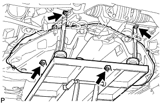
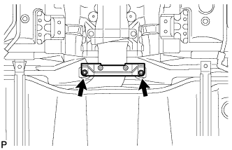
Temporarily install the 2 fuel tank bands with the 4 bolts.
-
Tighten the bolts in the front.
- Torque:
- 39 N*m { 408 kgf*cm, 30 ft.*lbf }
-
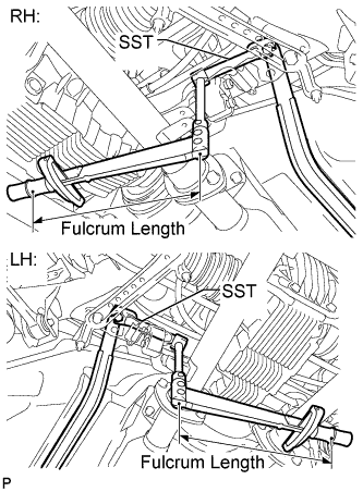
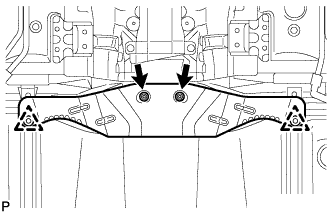
Using SST, a torque wrench and union nut wrench, tighten the bolts in the rear.
- SST
- 09961-00950
- Torque:
- without SST
- 39 N*m { 408 kgf*cm, 30 ft.*lbf }
- with SST
- 20 N*m { 204 kgf*cm, 15 ft.*lbf }
Tech Tips
-
Use a torque wrench with a fulcrum length of 180 mm (7.09 in).
-
Make sure union nut wrench, SST and torque wrench are connected in a straight line. Fulcrum Length
-
-
CONNECT FUEL TANK TO FILLER PIPE HOSE
-
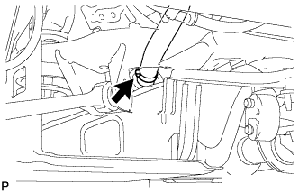
Connect the filler pipe hose to the fuel tank.
-
-
CONNECT NO. 1 FUEL TANK BREATHER TUBE SUB-ASSEMBLY
-
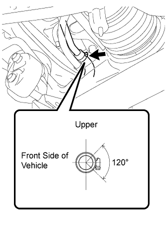
Connect the breather tube.
Tech Tips
The direction of the hose clamp is indicated in the illustration.
-
-
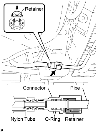
CONNECT FUEL TANK TO CANISTER TUBE SUB-ASSEMBLY
-
Connect the canister tube.
Note
-
Before installing the tube connectors to the pipes, check if there is any damage or foreign matter in the connectors.
-
After the connection, check if the connectors and pipes are securely connected by trying to pull them apart.
Tech Tips
Push the parts together firmly until a "click" sound is heard.
-
-
-
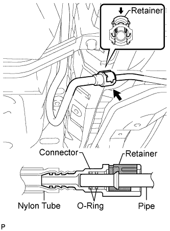
CONNECT FUEL TANK RETURN VENT TUBE
-
Connect the fuel tank return vent tube.
Note
-
Before installing the tube connectors to the pipes, check if there is any damage or foreign matter in the connectors.
-
After the connection, check if the connectors and pipes are securely connected by trying to pull them apart.
Tech Tips
Push the parts together firmly until a "click" sound is heard.
-
-
-
CONNECT FUEL TANK MAIN TUBE SUB-ASSEMBLY
-
Connect the fuel tank main tube LH.
Note
-
Before installing the tube connectors to the pipes, check if there is any damage or foreign matter in the connectors.
-
After the connection, check if the connectors and pipes are securely connected by trying to pull them apart.
Tech Tips
Push the parts together firmly until a "click" sound is heard.
-
-
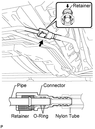
Connect the fuel tank main tube RH.
Note
-
Before installing the tube connectors to the pipes, check if there is any damage or foreign matter in the connectors.
-
After the connection, check if the connectors and pipes are securely connected by trying to pull them apart.
Tech Tips
Push the parts together firmly until a "click" sound is heard.
-
-
-
INSTALL FUEL TANK PROTECTOR BRACKET SIDE
-
Install the protector with the 2 nuts.
- Torque:
- 5.4 N*m { 55 kgf*cm, 48 in.*lbf }
-
-
INSTALL FUEL TANK FILLER PIPE PROTECTOR
-
Install the protector with the 2 clips and 2 nuts.
- Torque:
- 5.4 N*m { 55 kgf*cm, 48 in.*lbf }
-
-
INSTALL PROPELLER WITH CENTER BEARING SHAFT ASSEMBLY
-
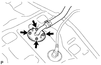
INSTALL FUEL SENDER GAUGE ASSEMBLY
-
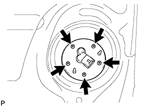
Install a new gasket and sender gauge to the fuel tank with the 5 screws.
- Torque:
- 1.5 N*m { 15 kgf*cm, 13 in.*lbf }
-
-
INSTALL REAR FLOOR SERVICE HOLE COVER
-
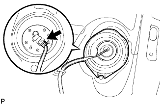
Connect the fuel sender gauge connector.
-
Install the service hole cover with new butyl tape.
-
-
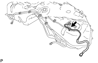
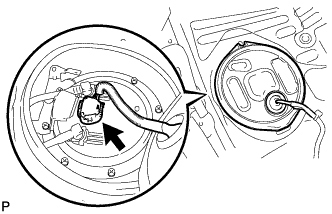
INSTALL FUEL SUCTION WITH PUMP AND GAUGE TUBE ASSEMBLY
-
Apply a light coat of gasoline to a new gasket, and install it to the fuel tank.
-
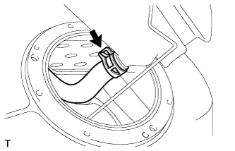
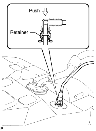
Connect the fuel hose, and install the fuel suction with pump and gauge tube to the fuel tank.
Note
-
Be careful not to bend the arm of the fuel sender gauge.
-
When connecting the fuel hose, do not forcibly pull the hose.
-
-
-
INSTALL FUEL TANK VENT TUBE SET PLATE
-
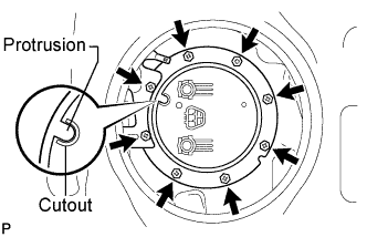
Install the No. 2 fuel tank protector and set plate with the 8 bolts.
- Torque:
- 6.0 N*m { 61 kgf*cm, 53 in.*lbf }
Tech Tips
Align the protrusion of the set plate with the cutout of the fuel suction with pump and gauge tube.
-
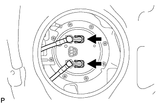
Install the fuel tank main tube and fuel tank return vent tube with the 2 tube joint clips.
Note
-
Check that there are no scratches or foreign objects on the connecting parts.
-
Check that the fuel tube joint is inserted securely.
-
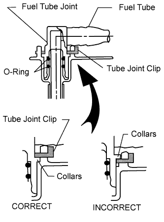
Check that the tube joint clips are on the collars of the fuel tube joints.
-
After installing the tube joint clips, check that the fuel tube joints have not been pulled off.
-
-
-
INSTALL REAR FLOOR NO. 2 SERVICE HOLE COVER
-
Connect the connector.
-
Install the service hole cover with new butyl tape.
-
-
INSTALL REAR NO. 1 AND NO. 2 SEAT ADJUSTER ASSEMBLY
-
for Power Seat:
-
for Ottoman:
-
-
INSTALL REAR SEAT CUSHION ASSEMBLY (for Fixed Seat Type)
-
INSTALL SERVICE PLUG GRIP
-
CONNECT CABLE TO AUXILIARY BATTERY NEGATIVE TERMINAL
Note
When disconnecting the cable, some systems need to be initialized after the cable is reconnected Click here.
-
INSTALL BATTERY SERVICE HOLE COVER LH
-

Text in Illustration *A for Standard *B for Ottoman Attach the battery service hole cover LH with the clip and fastening tape.
-
-
INSTALL DECK TRIM SIDE BOARD LH (w/o Spare Tire)
-

Attach the 2 clips to install the deck trim side board LH.
-
-
INSTALL DECK BOARD ASSEMBLY (w/o Spare Tire)

-
INSTALL LUGGAGE COMPARTMENT MAT SUB-ASSEMBLY (w/ Spare Tire)

-
ADD FUEL
-
INSPECT FOR FUEL LEAK
-
Connect the intelligent tester to the DLC3.
-
Turn the power switch on (IG).
Note
Do not start the engine.
-
Turn the intelligent tester on.
-
Select the following menus: Powertrain / Engine and ECT / Active Test / Control the Fuel Pump / Speed.
-
Check the fuel pump operation.
-
Check for pressure in the fuel inlet tube from the fuel line. Check that the sound of fuel flowing in the fuel tank can be heard.
If no sound can be heard, check the integration relay, fuel pump, ECM and wiring connector.
-
-
Check for fuel leaks.
-
Check that there are no fuel leaks anywhere on the system after performing maintenance.
If there is a fuel leak, repair or replace parts as necessary.
-
-