FUEL PUMP (for High Pressure) INSTALLATION

Tech Tips
When viewed from the rear of the engine assembly, Bank 1 is on the left side and Bank 2 is on the right side.
-
INSTALL FUEL PUMP ASSEMBLY (for Bank 1)
-
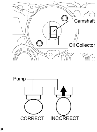
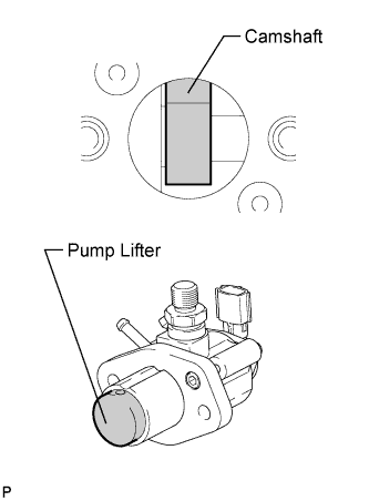
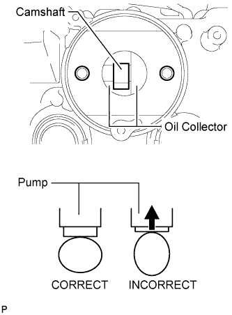
Turn the camshaft until the flat of the cam is facing the cylinder head cover's fuel pump attachment hole, as shown in the illustration.
Tech Tips
By not using the camshaft lobe to push up the pump lifter surface, it is easier to install the fuel pump and No. 3 fuel pipe later.
-
Pour 30 cc (1.8 cu. in.) of engine oil through the cylinder head cover's fuel pump attachment hole into the cylinder head oil collector.
-
Apply a coat of engine oil to the pump activation cam and pump lifter.
-
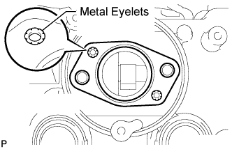
Install a new fuel pump insulator to the cylinder head cover. Then pass the 2 stud bolts through the holes of the fuel pump and set it on the insulator.
Note
Install the insulator so that the open sides of the metal eyelets are facing outward, as shown in the illustration.
-
Install the fuel pump with the 2 nuts.
- Torque:
- 25 N*m { 255 kgf*cm, 18 ft.*lbf }
-
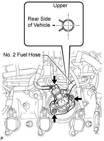
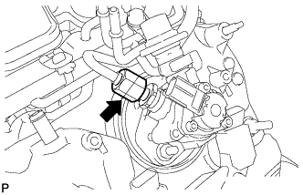
Connect the No. 2 fuel hose.
Tech Tips
As shown in the illustration.
-
Connect the fuel pump connector.
-
-
INSTALL FUEL PUMP ASSEMBLY (for Bank 2)
-
Turn the camshaft until the flat of the cam is facing the cylinder head cover's fuel pump attachment hole, as shown in the illustration.
Tech Tips
By not using the camshaft lobe to push up the pump lifter surface, it is easier to install the fuel pump and No. 2 fuel pipe later.
-
Pour 30 cc (1.8 cu. in.) of engine oil through the cylinder head cover's fuel pump attachment hole into the cylinder head oil collector.
-
Apply a coat of engine oil to the pump activation cam and pump lifter.
-
Install a new fuel pump insulator to the cylinder head cover. Then pass the 2 stud bolts through the holes of the fuel pump and set it on the insulator.
Note
Install the insulator so that the open sides of the metal eyelets are facing outward, as shown in the illustration.
-
Install the fuel pump with the 2 nuts.
- Torque:
- 25 N*m { 255 kgf*cm, 18 ft.*lbf }
-
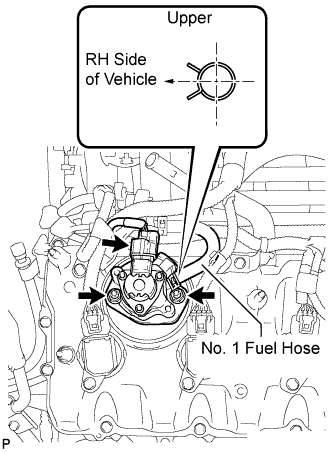
Connect the No. 1 fuel hose.
Tech Tips
As shown in the illustration.
-
Connect the fuel pump connector.
-
-
INSTALL NO. 3 FUEL PIPE SUB-ASSEMBLY
-
Install a new O-ring, new No. 1 backup ring, new No. 2 backup ring and a new E-ring to the No. 3 fuel pipe sub-assembly as shown in the illustration.
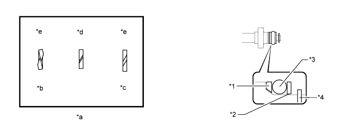
Text in Illustration *1 No. 1 Backup Ring *2 No. 2 Backup Ring *3 O-Ring *4 E-Ring *a Alignment Opening *b Overlapped *c Stretched *d CORRECT *e INCORRECT - - Note
-
Check that there is no foreign matter or damaged areas in the No. 3 fuel pipe sub-assembly O-ring groove.
-
Check that the No. 1 backup ring and No. 2 backup ring are installed in the correct direction.
-
Make sure that the backup rings and O-ring are installed in the correct order.
-
Check that the alignment openings of the backup rings are not overlapped or stretched as shown in the illustration.
-
After installing the O-ring, check that it is not contaminated with foreign matter and is not damaged.
-
-
Apply engine oil to the O-ring.
Note
Make sure there is no gasoline on the O-ring and inside the installation hole.
-
Temporarily install the No. 3 fuel pipe sub-assembly to the delivery pipe with the 2 bolts.
-
Temporarily install the No. 3 fuel pipe sub-assembly to the fuel pump.
Note
Be careful not to damage the sealing surface of the No. 3 fuel pipe sub-assembly when temporarily installing the No. 3 fuel pipe sub-assembly.
-
Tighten the 2 bolts in several passes.
- Torque:
- 10 N*m { 102 kgf*cm, 7 ft.*lbf }
-
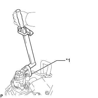
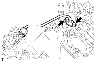
Text in Illustration *1 Union Nut Wrench Using a 19 mm union nut wrench, tighten the union nut.
- Torque:
- 30 N*m { 306 kgf*cm, 22 ft.*lbf }
Note
-
There must be absolutely no free play in the union on the fuel pump side. If the union on the fuel pump side has free play, replace the fuel pump.
-
Use the formula to calculate special torque values for situations where a union nut wrench is combined with a torque wrench Click here.
Tech Tips
Make sure use the union nut wrench and torque wrench are connected in a straight line.
-
Connect the fuel pump connector.
-
-
INSTALL NO. 2 FUEL PIPE SUB-ASSEMBLY
Tech Tips
The installation procedures are the same as for the No. 3 fuel pipe sub-assembly.
-
INSTALL FUEL PRESSURE PULSATION DAMPER ASSEMBLY