EXHAUST MANIFOLD INSTALLATION

Tech Tips
When viewed from the rear of the engine assembly, Bank 1 is on the left side and Bank 2 is on the right side.
-
INSTALL AIR FUEL RATIO SENSOR (for Bank 1 Sensor 1)
-
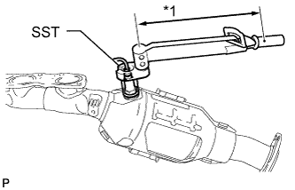
Text in Illustration *1 Fulcrum Length Using SST, install the air fuel ratio sensor to the exhaust manifold LH.
- SST
- 09224-00010
- Torque:
- without SST
- 44 N*m { 449 kgf*cm, 32 ft.*lbf }
- with SST
- 40 N*m { 408 kgf*cm, 30 ft.*lbf }
Tech Tips
-
Use a torque wrench with a fulcrum length of 300 mm (11.8 in.). When using a torque wrench with a fulcrum length that is not 300 mm (11.8 in.), calculate the torque specification for the torque wrench and SST based on the "without SST" torque specification Click here.
-
Make sure SST and the torque wrench are connected in a straight line.
-
-
INSTALL AIR FUEL RATIO SENSOR (for Bank 2 Sensor 1)
-
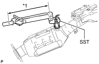
Text in Illustration *1 Fulcrum Length Using SST, install the air fuel ratio sensor to the exhaust manifold RH.
- SST
- 09224-00010
- Torque:
- without SST
- 44 N*m { 449 kgf*cm, 32 ft.*lbf }
- with SST
- 40 N*m { 408 kgf*cm, 30 ft.*lbf }
Tech Tips
-
Use a torque wrench with a fulcrum length of 300 mm (11.8 in.). When using a torque wrench with a fulcrum length that is not 300 mm (11.8 in.), calculate the torque specification for the torque wrench and SST based on the "without SST" torque specification Click here.
-
Make sure SST and the torque wrench are connected in a straight line.
-
-
INSTALL EXHAUST MANIFOLD SUB-ASSEMBLY LH
-
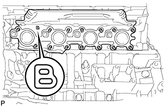
Place a new gasket on the cylinder head with the "B" mark facing the manifold side.
Note
Be careful of the installation direction.
-
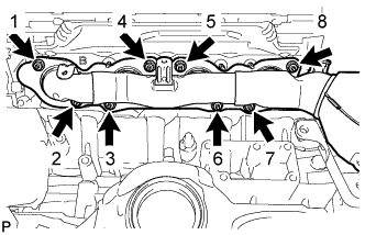
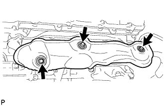
Temporarily install the exhaust manifold, and then uniformly tighten 8 new nuts in several steps, in the sequence shown in the illustration.
- Torque:
- 21 N*m { 214 kgf*cm, 15 ft.*lbf }
-
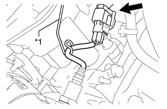
Text in Illustration *1 Bracket Connect the air fuel ratio sensor connector.
Tech Tips
Hook the wire harness to the bracket.
-
-
INSTALL EXHAUST MANIFOLD SUB-ASSEMBLY RH
-
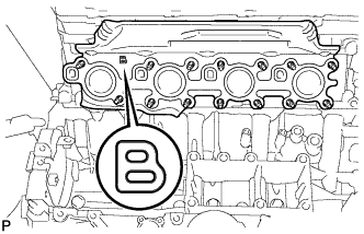
Place a new gasket on the cylinder head with the "B" mark facing the manifold side.
Note
Be careful of the installation direction.
-
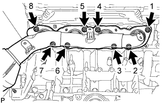
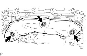
Temporarily install the exhaust manifold, and then uniformly tighten 8 new nuts in several steps, in the sequence shown in the illustration.
- Torque:
- 21 N*m { 214 kgf*cm, 15 ft.*lbf }
-
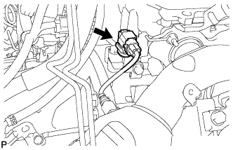
Connect the air fuel ratio sensor connector.
-
-
INSTALL FRONT NO. 1 ENGINE MOUNTING BRACKET LH
-
Install the front No. 1 engine mounting bracket LH with the 5 bolts.
- Torque:
- 35 N*m { 357 kgf*cm, 26 ft.*lbf }
-
-
INSTALL FRONT NO. 1 ENGINE MOUNTING BRACKET RH
-
Install the front No. 1 engine mounting bracket RH with the 5 bolts.
- Torque:
- 35 N*m { 357 kgf*cm, 26 ft.*lbf }
-
-
INSTALL FRONT ENGINE MOUNTING INSULATOR
-
Install the 2 spacers and 2 front engine mounting insulators with the 2 nuts.
- Torque:
- 35 N*m { 357 kgf*cm, 26 ft.*lbf }
-
-
INSTALL NO. 2 EXHAUST MANIFOLD HEAT INSULATOR
-
Install the heat insulator with the 3 bolts.
- Torque:
- 10 N*m { 102 kgf*cm, 7 ft.*lbf }
-
-
INSTALL NO. 1 EXHAUST MANIFOLD HEAT INSULATOR
-
Install the heat insulator with the 3 bolts.
- Torque:
- 10 N*m { 102 kgf*cm, 7 ft.*lbf }
-
-
INSTALL ENGINE OIL LEVEL DIPSTICK GUIDE
-
Apply a light coat of engine oil to a new O-ring.
-
Install the O-ring to the engine oil level dipstick guide.
-
Install the engine oil level dipstick guide with the bolt.
- Torque:
- 10 N*m { 102 kgf*cm, 7 ft.*lbf }
-
Install the engine oil level dipstick.
-
-
INSTALL FRONT FRAME ASSEMBLY
-
Slowly lower the engine and set it to the front frame assembly.
-
Install the 4 nuts.
- Torque:
- 70 N*m { 714 kgf*cm, 52 ft.*lbf }
-
Attach the 2 clips and connect the heater wire connector.
-
-
INSTALL ENGINE AND TRANSMISSION