FUEL RELIEF VALVE INSTALLATION

-
INSTALL FUEL RELIEF VALVE ASSEMBLY
-
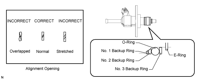
Install a new O-ring, new backup rings (No. 1, No. 2 and No. 3) and a new E-ring to the fuel relief valve as shown in the illustration.
Note
-
Check that there is no foreign matter or damaged areas in the relief valve's O-ring groove.
-
Check that the No. 1 and No. 2 backup rings are installed in the correct direction.
-
Make sure that the backup rings and O-ring are installed in the correct order.
-
Check that the alignment openings of the backup rings are not overlapped or stretched as shown in the illustration.
-
After installing the O-ring, check that it is not contaminated with foreign matter and is not damaged.
-
Check that the No. 3 fuel pipe installation end is not contaminated with foreign matter and is not damaged.
-
-
Fix the delivery pipe between aluminum plates in a vise.
Note
Do not overtighten the vise.
-
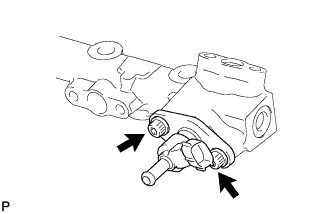
Apply engine oil to the O-ring. Using a 5 mm hexagon socket wrench, install the fuel relief valve to the fuel delivery pipe with the 2 bolts.
- Torque:
- 9.0 N*m { 92 kgf*cm, 80 in.*lbf }
Note
Make sure there is no gasoline on the O-ring and inside the installation hole.
-
-
INSTALL FUEL DELIVERY PIPE
-
Install 4 new injector vibration insulators to the cylinder head.
-
Apply lubricant to the fuel injector seals and installation holes.
-
Install the fuel delivery pipe (with fuel injector assemblies) to the cylinder head with the 5 bolts.
- Torque:
- 21 N*m { 214 kgf*cm, 15 ft.*lbf }
Note
-
If a fuel injector assembly is dropped or the tip of the fuel injector assembly is struck, replace it with a new one.
-
Check that there is no foreign matter or damage to the fuel injector assembly insertion hole of the cylinder head.
-
When inserting the fuel delivery pipe, push it in evenly without tilting it.
-
Connect the 4 fuel injector connectors.
-
Connect the No. 3 fuel hose and fuel relief valve connector.
-
-
INSTALL NO. 4 FUEL PIPE SUB-ASSEMBLY
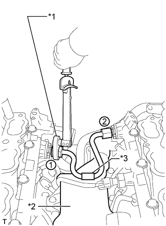
Text in Illustration *1 Union Nut Wrench *2 Separator Case *3 Fuel Pipe Protector
-
Temporarily install the No. 4 fuel pipe sub-assembly.
-
Using a 19 mm union nut wrench, tighten the No. 4 fuel pipe sub-assembly in the order shown in the illustration.
- Torque:
- 30 N*m { 306 kgf*cm, 22 ft.*lbf }
Note
-
After installing the No. 4 fuel pipe sub-assembly, check that the fuel pipe protector contacts with the separator case.
-
Use the formula to calculate special torque values for situations where a union nut wrench is combined with a torque wrench Click here.
Tech Tips
Make sure use the union nut wrench and torque wrench are connected in a straight line.
-
-
INSTALL NO. 2 ENGINE COVER SUB-ASSEMBLY LH
-
INSTALL NO. 2 ENGINE COVER SUB-ASSEMBLY
-
INSTALL NO. 1 ENGINE COVER SUB-ASSEMBLY
-
INSTALL NO. 2 FUEL PIPE SUB-ASSEMBLY
-
INSTALL FUEL PRESSURE PULSATION DAMPER ASSEMBLY