FUEL PRESSURE PULSATION DAMPER INSTALLATION

Tech Tips
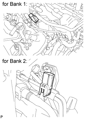
When viewed from the rear of the engine assembly, Bank 1 is on the left side and Bank 2 is on the right side.
Note
While the auxiliary battery is connected, even if the power switch is off, the brake control system activates when the brake pedal is depressed or the door courtesy switch turns on. Therefore during servicing of the brake system components, do not operate the brake pedal and open / close the doors while the battery is connected.
-
INSTALL FUEL PRESSURE PULSATION DAMPER ASSEMBLY
-
Apply a light coat of engine oil to the threads and gasket seating surfaces of the 2 fuel pressure pulsation damper assemblies.
-
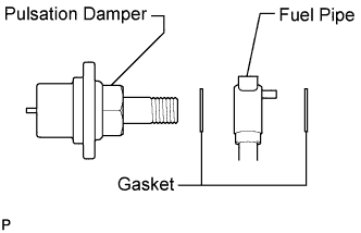
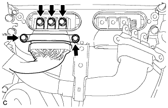
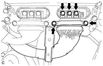
Temporarily install each dampers together with 2 new gaskets and the fuel pipe to the fuel pump.
-
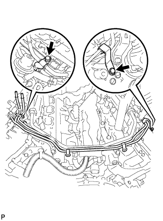
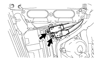
Install the 2 clamp bolts.
- Torque:
- 10 N*m { 102 kgf*cm, 7 ft.*lbf }
-
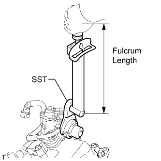
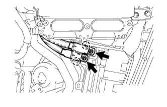
Using SST, tighten the 2 dampers.
- SST
- 09612-24014 ( 09617-24011 )
- Torque:
- without SST
- 36 N*m { 367 kgf*cm, 27 ft.*lbf }
- with SST
- 31 N*m { 313 kgf*cm, 23 ft.*lbf }
Tech Tips
-
Use a torque wrench with a fulcrum length of 300 mm (11.8 in.). When using a torque wrench with a fulcrum length that is not 300 mm (11.8 in.), calculate the torque specification for the torque wrench and SST based on the "without SST" torque specification Click here.
-
Make sure SST and the torque wrench are connected in a straight line.
-
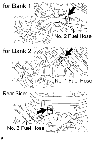
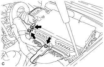
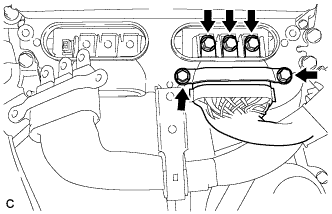
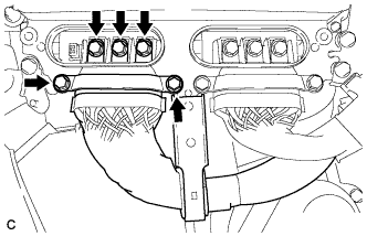
Connect the 3 fuel hoses.
-
Connect the 2 delivery pipe connectors to the delivery pipe.
-
-
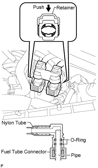
CONNECT NO. 1 FUEL HOSE
-
Push in the tube connector to the pipe until the tube connector makes a "click" sound.
-
Push down on the retainer to lock it in place.
Note
-
Check that there is no damage or foreign objects on the connected part of the fuel pipe.
-
After connecting, check that the fuel tube connector and the pipe are securely connected by pulling on them.
-
-
-
INSTALL NO. 6 COVER SUB-ASSEMBLY (for RHD)
-
Install the No. 6 cover.
-
-
INSTALL ENGINE COVER SUB-ASSEMBLY LH (for RHD)
-
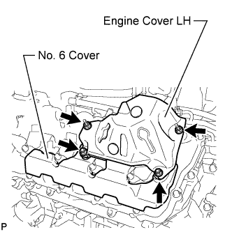
Install the engine cover LH with the 4 nuts.
- Torque:
- 21 N*m { 214 kgf*cm, 15 ft.*lbf }
-
-
INSTALL NO. 5 COVER SUB-ASSEMBLY (for LHD)
-
Install the No. 5 cover.
-
-
INSTALL ENGINE COVER SUB-ASSEMBLY RH (for LHD)
-
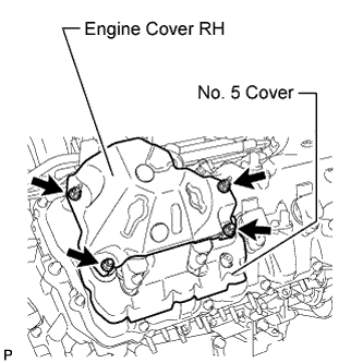
Install the engine cover RH with the 4 nuts.
- Torque:
- 21 N*m { 214 kgf*cm, 15 ft.*lbf }
-
-
INSTALL ENGINE OIL LEVEL DIPSTICK GUIDE
-
Apply a light coat of engine oil to a new O-ring.
-
Install the O-ring to the engine oil level dipstick guide.
-
Install the engine oil level dipstick guide with the bolt.
- Torque:
- 10 N*m { 102 kgf*cm, 7 ft.*lbf }
-
Install the engine oil level dipstick.
-
-
INSTALL INVERTER COOLING PIPE BRACKET (for RHD)
-
Attach the clamp of the frame wire and the clamp of the air conditioning harness to the inverter cooling pipe bracket.
-
Install the inverter cooling pipe bracket to the inverter with converter assembly with the bolt.
- Torque:
- 8.0 N*m { 82 kgf*cm, 71 in.*lbf }
-
Attach the clamp of the No. 2 inlet inverter cooling hose to the inverter cooling pipe bracket.
-
Attach the 2 clamps of the air conditioning harness to the No. 1 relay block.
-
-
CONNECT FRAME WIRE (for RHD)
-
Attach the 2 claws of the frame wire to the No. 1 relay block.
-
Install the frame wire to the No. 1 relay block with the 2 nuts.
- Torque:
- 13 N*m { 130 kgf*cm, 10 ft.*lbf }
-
Install the No. 1 relay block cover.
-
-
CONNECT GENERATOR CABLE (for RHD)
CAUTION:
Wear insulating gloves.
-
Connect the generator cable to the inverter with converter assembly.
-
Using an insulated tool, secure the generator cable to the inverter with converter assembly with the 5 bolts.
- Torque:
- 8.0 N*m { 82 kgf*cm, 71 in.*lbf }
Note
-
When installing the bolts that secure the cable, do not damage anything inside the inverter with converter assembly.
-
Make sure that no foreign matter is present on the terminal block.
-
Be sure to tighten the bolt to the specified torque. Failure to do so may damage the bolt.
-
-
CONNECT MOTOR CABLE (for RHD)
CAUTION:
Wear insulating gloves.
-
Connect the motor cable to the inverter with converter assembly.
-
Using an insulated tool, secure the motor cable to the inverter with converter assembly with the 5 bolts.
- Torque:
- 8.0 N*m { 82 kgf*cm, 71 in.*lbf }
Note
-
When installing the bolts that secure the cable, do not damage anything inside the inverter with converter assembly.
-
Make sure that no foreign matter is present on the terminal block.
-
Be sure to tighten the bolt to the specified torque. Failure to do so may damage the bolt.
-
Install the motor cable bracket with the 3 bolts.
- Torque:
- 8.0 N*m { 82 kgf*cm, 71 in.*lbf }
-
-
INSTALL INVERTER TERMINAL COVER (for RHD)
CAUTION:
Wear insulating gloves.
-
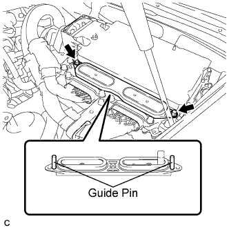
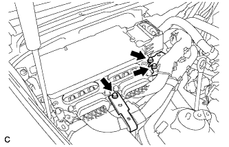
Set the inverter terminal cover to the inverter with converter assembly.
Note
-
Check that the sealing rubber is securely installed to the inverter terminal cover before installing the cover.
-
Making sure that there are no foreign objects on the waterproofed parts before installing the inverter terminal cover.
-
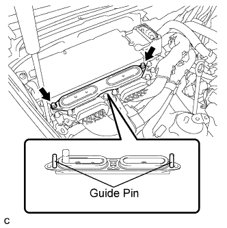
Install the inverter terminal cover while inserting the guide pins on both sides of the cover into guide pin holes of the inverter case.
-
When removing the inverter terminal cover, do not bend the connector terminals around the interlock part.
-
-
Push in both ends of the inverter terminal cover horizontally by hand.
Note
-
Insert the inverter terminal cover horizontally to prevent it from tilting. Failure to do so may damage the inverter terminal cover guide pins.
-
Make sure that both the inverter terminal cover bolt holes are aligned and in contact with the holes in the inverter case.
-
-
Using an insulated tool, secure the inverter terminal cover to the inverter with converter assembly with the 2 bolts.
- Torque:
- 8.0 N*m { 82 kgf*cm, 71 in.*lbf }
-
-
CONNECT FRAME WIRE (for LHD)
-
Attach the 2 claws of the frame wire to the No. 1 relay block.
-
Install the frame wire to the No. 1 relay block with the 2 nuts.
- Torque:
- 13 N*m { 130 kgf*cm, 10 ft.*lbf }
-
Install the No. 1 relay block cover.
-
-
CONNECT INLET INVERTER COOLING PIPE (for LHD)
-
Install the inlet inverter cooling pipe with the 2 bolts.
- Torque:
- 13 N*m { 127 kgf*cm, 9 ft.*lbf }
-
-
CONNECT GENERATOR CABLE (for LHD)
CAUTION:
Wear insulating gloves.
-
Using an insulated tool, connect the generator cable to the inverter with converter assembly.
-
Secure the generator cable to the inverter with converter assembly with the 5 bolts.
- Torque:
- 8.0 N*m { 82 kgf*cm, 71 in.*lbf }
Note
-
When installing the bolts that secure the cable, do not damage anything inside the inverter with converter assembly.
-
Make sure that no foreign matter is present on the terminal block.
-
Be sure to tighten the bolt to the specified torque. Failure to do so may damage the bolt.
-
-
CONNECT MOTOR CABLE (for LHD)
CAUTION:
Wear insulating gloves.
-
Using an insulated tool, connect the motor cable to the inverter with converter assembly.
-
Secure the motor cable to the inverter with converter assembly with the 5 bolts.
- Torque:
- 8.0 N*m { 82 kgf*cm, 71 in.*lbf }
Note
-
When installing the bolts that secure the cable, do not damage anything inside the inverter with converter assembly.
-
Make sure that no foreign matter is present on the terminal block.
-
Be sure to tighten the bolt to the specified torque. Failure to do so may damage the bolt
-
Install the motor cable bracket with the 3 bolts.
- Torque:
- 8.0 N*m { 82 kgf*cm, 71 in.*lbf }
-
-
INSTALL INVERTER TERMINAL COVER (for LHD)
CAUTION:
Wear insulating gloves.
-
Set the inverter terminal cover to the inverter with converter assembly.
Note
-
Check that the sealing rubber is securely installed to the inverter terminal cover before installing the cover.
-
Making sure that there are no foreign objects on the waterproofed parts before installing the inverter terminal cover.
-
Install the inverter terminal cover while inserting the guide pins on both sides of the cover into guide pin holes of the inverter case.
-
When removing the inverter terminal cover, do not bend the connector terminals around the interlock part.
-
-
Push in both ends of the inverter terminal cover horizontally by hand.
Note
-
Insert the inverter terminal cover horizontally to prevent it from tilting. Failure to do so may damage the inverter terminal cover guide pins.
-
Make sure that both the inverter terminal cover bolt holes are aligned and in contact with the holes in the inverter case.
-
-
Using an insulated tool, secure the inverter terminal cover to the inverter with converter assembly with the 2 bolts.
- Torque:
- 8.0 N*m { 82 kgf*cm, 71 in.*lbf }
-
-
INSTALL INVERTER COVER ASSEMBLY LH (for RHD)
-
Install the inverter cover assembly LH and attach the 2 clips.
-
-
INSTALL MOTOR CABLE COVER LH (for RHD)
-
Install the motor cable cover LH with the 2 clips.
-
-
INSTALL COWL TOP VENTILATOR LOUVER LH (for RHD)
-
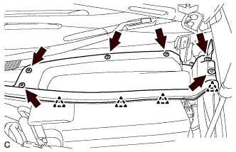
Install the hood to cowl top seal with the 4 clips.
-
Install the cowl top ventilator louver LH with the 6 clips.
-
-
INSTALL INVERTER COVER ASSEMBLY RH (for LHD)
-
Install the inverter cover assembly RH and attach the 2 clips.
-
-
INSTALL MOTOR CABLE COVER RH (for LHD)
-
Install the motor cable cover RH with the 2 clips.
-
-
INSTALL COWL TOP VENTILATOR LOUVER RH (for LHD)
-
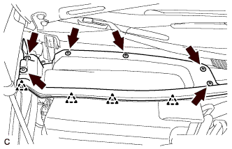
Install the hood to cowl top seal with the 4 clips.
-
Install the cowl top ventilator louver RH with the 6 clips.
-
-
INSTALL INTAKE MANIFOLD
-
INSPECT FOR FUEL LEAK
-
Connect the intelligent tester to the DLC3.
-
Turn the power switch on (IG).
Note
Do not start the engine.
-
Turn the intelligent tester on.
-
Select the following menus: Powertrain / Engine and ECT / Active Test / Control the Fuel Pump / Speed.
-
Check the fuel pump operation.
-
Check for pressure in the fuel inlet tube from the fuel line. Check that the sound of fuel flowing in the fuel tank can be heard.
If no sound can be heard, check the integration relay, fuel pump, ECM and wiring connector.
-
-
Check for fuel leaks.
-
Check that there are no fuel leaks anywhere on the system after performing maintenance.
If there is a fuel leak, repair or replace parts as necessary.
-
-