FUEL INJECTOR (for Direct Injection) INSTALLATION

-
INSTALL FUEL DELIVERY PIPE PLUG
-
Apply engine oil to the threaded portion of the fuel delivery pipe.
Note
Make sure there is no gasoline on the threaded part of the fuel delivery pipe plug and fuel delivery pipe.
-
Install 2 new gaskets and the 2 fuel delivery pipe plugs to the fuel delivery pipe and No. 2 fuel delivery pipe.
- Torque:
- 33 N*m { 337 kgf*cm, 24 ft.*lbf }
-
-
INSTALL FUEL PIPE SUPPORT SUB-ASSEMBLY
-
Install 2 new O-rings, 2 new No. 1 backup rings, 2 new No. 2 backup rings and 2 new E-rings to the 2 fuel pipe support sub-assemblies as shown in the illustration.
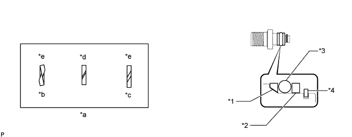
Text in Illustration *1 No. 1 Backup Ring *2 No. 2 Backup Ring *3 O-Ring *4 E-Ring *a Alignment Opening *b Overlapped *c Stretched *d CORRECT *e INCORRECT - - Note
-
Check that there is no foreign matter or damaged areas in the fuel pipe support sub-assembly O-ring groove.
-
Check that the No. 1 backup ring is installed in the correct direction.
-
Make sure that the backup rings and O-ring are installed in the correct order.
-
Check that the alignment openings of the backup rings are not overlapped or stretched as shown in the illustration.
-
After installing the O-ring, check that it is not contaminated with foreign matter and is not damaged.
-
-
Apply engine oil to the O-ring.
Note
Make sure there is no gasoline on the O-ring and inside the installation hole.
-
Install the 2 fuel pipe support sub-assemblies to the fuel delivery pipe and No. 2 fuel delivery pipe with the 4 bolts.
- Torque:
- 10 N*m { 102 kgf*cm, 7 ft.*lbf }
-
-
INSTALL FUEL INJECTOR SEAL
-
Text in Illustration *a Clean Area Apply engine conditioner to the clean area shown in the illustration. Using a piece of cloth, clean carbon deposits from the fuel injector assembly and its grooves.
Note
-
Do not clean the tip of the fuel injector assembly.
-
Do not use a wire brush to clean the fuel injector assembly.
-
If a fuel injector assembly is dropped or the tip of the fuel injector assembly is struck, replace it with a new one.
-
-
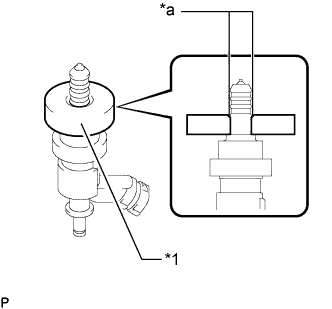
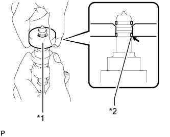
Text in Illustration *1 SST (Guide) *a Tapered Inner Portion Apply engine oil to the fuel injector assembly contact surface of SST (guide). Then attach SST (guide) to the fuel injector assembly with the tapered inner portion facing the tip of the fuel injector assembly as shown in the illustration.
- SST
- 09260-39015 ( 09268-03020 )
-
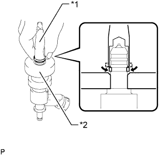
Text in Illustration *1 SST (Holder) *2 Fuel Injector Seal *a CORRECT *b INCORRECT Install a new fuel injector seal to SST (holder).
- SST
- 09260-39015 ( 09268-03010 )
Note
Be careful not to install the fuel injector seal to SST (holder) at an angle. Doing so will stretch the fuel injector seal and correcting this problem is very complicated.
-
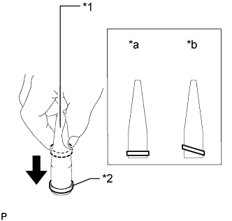
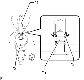
Text in Illustration *1 SST (Holder) *2 SST (Guide) Install SST (holder with fuel injector seal) to the tip of the fuel injector assembly. Slide the seal downward into the fuel injector assembly groove (fuel injector assembly connector side) with your fingers as shown in the illustration.
- SST
- 09260-39015 ( 09268-03020, 09268-03010 )
Tech Tips
Check that the seal covers the circumference of the fuel injector assembly groove as shown in the illustration.
-
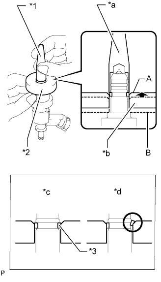
Text in Illustration *1 SST (Holder) *2 SST (Guide) *3 Fuel Injector Seal *a Gently Press *b Slowly Slide *c CORRECT *d INCORRECT Using SST (holder), gently press downward on the fuel injector seal (fuel injector assembly connector side). Then slowly slide SST (guide) towards the fuel injector assembly tip to settle the seal into the fuel injector assembly groove.
- SST
- 09260-39015 ( 09268-03020, 09268-03010 )
Note
Be careful that the fuel injector seal is not pinched between SST (guide) and the fuel injector assembly groove. Replace the fuel injector seal if it becomes damaged.
Tech Tips
-
When using SST (guide) to settle the fuel injector seal into the groove, SST (guide) only needs to be slid upward to the position labeled A in the illustration.
-
After using SST (guide) to settle the fuel injector seal into the groove, return SST (guide) to its position labeled B in the illustration.
-
Text in Illustration *1 SST (Holder) *2 Fuel Injector Seal *a CORRECT *b INCORRECT Install a new fuel injector seal to SST (holder).
- SST
- 09260-39015 ( 09268-03010 )
Note
Be careful not to install the fuel injector seal to SST (holder) at an angle. Doing so will stretch the fuel injector seal and correcting this problem is very complicated.
-
Text in Illustration *1 SST (Holder) *2 SST (Guide) *3 Fuel Injector Seal *a Welded Groove Install SST (holder with fuel injector seal) to the tip of the fuel injector assembly. Slide the fuel injector seal downward into the fuel injector assembly groove (fuel injector assembly tip side) with your fingers as shown in the illustration.
- SST
- 09260-39015 ( 09268-03020, 09268-03010 )
Note
Make sure that the fuel injector seal does not slip into the welded groove of the fuel injector assembly shown in the illustration. If it does, replace it with a new one.
Tech Tips
Check that the fuel injector seal covers the circumference of the fuel injector assembly groove as shown in the illustration.
-
Text in Illustration *1 SST (Guide) *2 Fuel Injector Seal Slowly slide SST (guide) towards the tip of the fuel injector assembly. When the fuel injector assembly contact surface of SST (guide) aligns with the fuel injector seal (fuel injector assembly connector side) as shown in the illustration, hold the position for 5 seconds or more to fully align the fuel injector seal into the fuel injector assembly groove.
- SST
- 09260-39015 ( 09268-03020 )
Note
Be careful that the fuel injector seal is not pinched between SST (guide) and the fuel injector assembly groove. Replace the seal if it becomes damaged.
Tech Tips
-
Set SST (guide) so that its bottom surface and the fuel injector seal are flush.
-
If it is difficult to slide SST upward, slowly wiggle it from side to side while sliding it up the fuel injector assembly little by little.
-
Text in Illustration *1 SST (Holder) *2 SST (Guide) *3 Fuel Injector Seal *a Gently Press *b Slide *c CORRECT *d INCORRECT Using SST (holder), gently press downward on the fuel injector seal (fuel injector assembly tip side). Then slowly slide SST (guide) towards the fuel injector assembly tip to settle the fuel injector seal into the fuel injector assembly groove.
- SST
- 09260-39015 ( 09268-03020, 09268-03010 )
Note
Be careful that the fuel injector seal is not pinched between SST (guide) and the fuel injector assembly groove. Replace the fuel injector seal if it becomes damaged.
-
Text in Illustration *1 SST (Guide) *2 Fuel Injector Seal Slowly slide SST (guide) towards the tip of the fuel injector assembly. When the fuel injector assembly contact surface of SST (guide) aligns with the fuel injector seal (fuel injector assembly tip side) as shown in the illustration, hold the position for 5 seconds or more to fully align the fuel injector seal into the fuel injector assembly groove.
- SST
- 09260-39015 ( 09268-03020 )
Note
Be careful that the fuel injector seal is not pinched between SST (guide) and the fuel injector assembly groove. Replace the fuel injector seal if it becomes damaged.
Tech Tips
-
Set SST (guide) so that its bottom surface and the fuel injector seal's bottom surface are flush.
-
If it is difficult to slide SST upward, slowly wiggle it from side to side while sliding it up the fuel injector assembly little by little.
-
Text in Illustration *a CORRECT *b INCORRECT *c Protruding *d Deformed After installing the fuel injector seals, check that the fuel injector seals are not scratched, deformed or protruding from the fuel injector assembly grooves.
If the fuel injector seal is scratched, deformed or protruding from the groove, replace it with a new one.
-
-
INSTALL FUEL INJECTOR ASSEMBLY
-
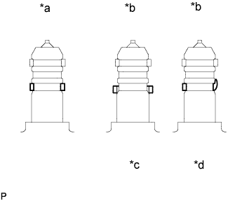
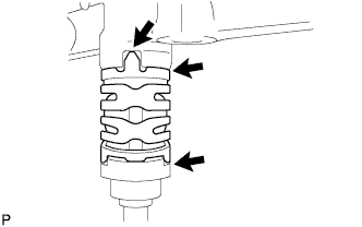
Install a new O-ring, new No. 1 backup ring, new No. 2 backup ring, new No. 3 backup ring and a new E-ring to the fuel injector assembly as shown in the illustration.
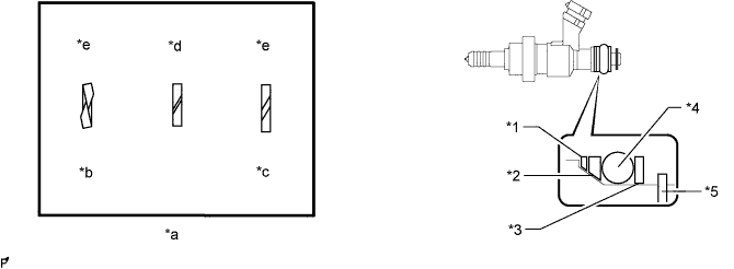
Text in Illustration *1 No. 1 Backup Ring *2 No. 2 Backup Ring *3 No. 3 Backup Ring *4 O-Ring *5 E-Ring - - *a Alignment Opening *b Overlapped *c Stretched *d CORRECT *e INCORRECT - - Note
-
Check that there is no foreign matter or damaged areas in the fuel injector assembly O-ring groove.
-
Check that the No. 1 backup ring and No. 2 backup ring are installed in the correct direction.
-
Make sure that the No. 1 backup ring, No. 2 backup ring, No. 3 backup ring and O-ring are installed in the correct order.
-
Check that the alignment openings of the No. 1 backup ring, No. 2 backup ring and No. 3 backup ring are not overlapped or stretched as shown in the illustration.
-
After installing the O-ring, check that it is not contaminated with foreign matter and is not damaged.
-
-
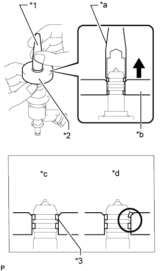
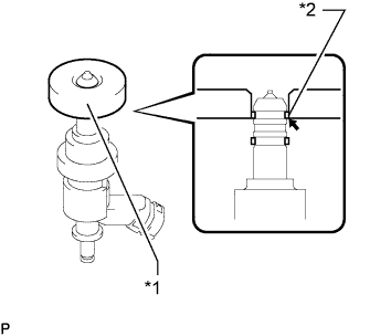
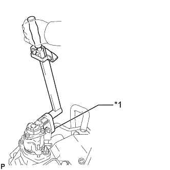
Install the injector nozzle holder clamp.
-
Text in Illustration *1 Insulator Color Apply engine oil to the O-ring. Install the nozzle holder clamp by aligning the protruding part of the clamp to the notch of the fuel delivery pipe.
Note
-
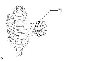
-
Make sure there is no gasoline on the O-ring and inside the installation hole.
-
The fuel injector assembly connectors can be differentiated by the color of the insulators, which are black, yellow, green or brown. Install the fuel injector assemblies so that insulators are the same color for a given bank.
-
Make sure that there is no gap between the fuel delivery pipe and injector nozzle holder clamp.
-
Check that there is no foreign matter or damage to the fuel injector assembly insertion hole of the fuel delivery pipe.
-
Insert the fuel injector assembly straight into the fuel delivery pipe without tilting it.
-
-
-
-
INSTALL FUEL DELIVERY PIPE
-
Install 4 new injector vibration insulators to the cylinder head.
-
Apply lubricant to the fuel injector seals and installation holes.
-
Install the fuel delivery pipe (with fuel injector assemblies) to the cylinder head with the 5 bolts.
- Torque:
- 21 N*m { 214 kgf*cm, 15 ft.*lbf }
Note
-
If a fuel injector assembly is dropped or the tip of the fuel injector assembly is struck, replace it with a new one.
-
Check that there is no foreign matter or damage to the fuel injector assembly insertion hole of the cylinder head.
-
When inserting the fuel delivery pipe, push it in evenly without tilting it.
-
Connect the 4 fuel injector connectors.
-
Connect the No. 3 fuel hose and fuel relief valve connector.
-
-
INSTALL NO. 2 FUEL DELIVERY PIPE
-
Install 4 new injector vibration insulators to the cylinder head.
-
Apply lubricant to the fuel injector seals and installation holes.
-
Install the No. 2 fuel delivery pipe (with fuel injector assemblies) to the cylinder head with the 5 bolts.
- Torque:
- 21 N*m { 214 kgf*cm, 15 ft.*lbf }
Note
-
If a fuel injector assembly is dropped or the tip of the fuel injector assembly is struck, replace it with a new one.
-
Check that there is no foreign matter or damage to the fuel injector assembly insertion hole of the cylinder head.
-
When inserting the No. 2 fuel delivery pipe, push it in evenly without tilting it.
-
Connect the 4 fuel injector connectors.
-
Connect the fuel pressure sensor connector.
-
-
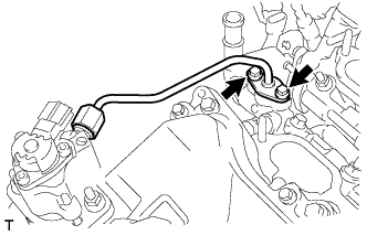
INSTALL NO. 4 FUEL PIPE SUB-ASSEMBLY
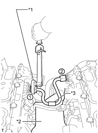
Text in Illustration *1 Union Nut Wrench *2 Separator Case *3 Fuel Pipe Protector
-
Temporarily install the No. 4 fuel pipe sub-assembly.
-
Using a 19 mm union nut wrench, tighten the No. 4 fuel pipe sub-assembly in the order shown in the illustration.
- Torque:
- 30 N*m { 306 kgf*cm, 22 ft.*lbf }
Note
-
After installing the No. 4 fuel pipe sub-assembly, check that the fuel pipe protector contacts with the separator case.
-
Use the formula to calculate special torque values for situations where a union nut wrench is combined with a torque wrench Click here.
Tech Tips
Make sure use the union nut wrench and torque wrench are connected in a straight line.
-
-
INSTALL NO. 2 ENGINE COVER SUB-ASSEMBLY LH
-
INSTALL NO. 2 ENGINE COVER SUB-ASSEMBLY
-
INSTALL NO. 1 ENGINE COVER SUB-ASSEMBLY
-
INSTALL NO. 3 FUEL PIPE SUB-ASSEMBLY
-
Install a new O-ring, new No. 1 backup ring, new No. 2 backup ring and a new E-ring to the No. 3 fuel pipe sub-assembly as shown in the illustration.
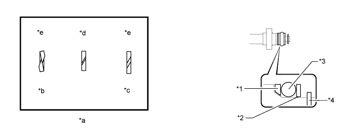
Text in Illustration *1 No. 1 Backup Ring *2 No. 2 Backup Ring *3 O-Ring *4 E-Ring *a Alignment Opening *b Overlapped *c Stretched *d CORRECT *e INCORRECT - - Note
-
Check that there is no foreign matter or damaged areas in the No. 3 fuel pipe sub-assembly O-ring groove.
-
Check that the No. 1 backup ring and No. 2 backup ring are installed in the correct direction.
-
Make sure that the backup rings and O-ring are installed in the correct order.
-
Check that the alignment openings of the backup rings are not overlapped or stretched as shown in the illustration.
-
After installing the O-ring, check that it is not contaminated with foreign matter and is not damaged.
-
-
Apply engine oil to the O-ring.
Note
Make sure there is no gasoline on the O-ring and inside the installation hole.
-
Temporarily install the No. 3 fuel pipe sub-assembly to the delivery pipe with the 2 bolts.
-
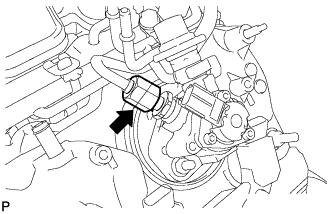
Temporarily install the No. 3 fuel pipe sub-assembly to the fuel pump.
Note
Be careful not to damage the sealing surface of the No. 3 fuel pipe sub-assembly when temporarily installing the No. 3 fuel pipe sub-assembly.
-
Tighten the 2 bolts in several passes.
- Torque:
- 10 N*m { 102 kgf*cm, 7 ft.*lbf }
-
Text in Illustration *1 Union Nut Wrench Using a 19 mm union nut wrench, tighten the union nut.
- Torque:
- 30 N*m { 306 kgf*cm, 22 ft.*lbf }
Note
-
There must be absolutely no free play in the union on the fuel pump side. If the union on the fuel pump side has free play, replace the fuel pump.
-
Use the formula to calculate special torque values for situations where a union nut wrench is combined with a torque wrench Click here.
Tech Tips
Make sure use the union nut wrench and torque wrench are connected in a straight line.
-
Connect the fuel pump connector.
-
-
INSTALL NO. 2 FUEL PIPE SUB-ASSEMBLY
Tech Tips
The installation procedures are the same as for the No. 3 fuel pipe sub-assembly.
-
INSTALL FUEL PRESSURE PULSATION DAMPER ASSEMBLY
-
INSPECT FOR FUEL LEAK
-
Connect the intelligent tester to the DLC3.
-
Turn the power switch on (IG).
Note
Do not start the engine.
-
Turn the intelligent tester on.
-
Select the following menus: Powertrain / Engine and ECT / Active Test / Control the Fuel Pump / Speed.
-
Check the fuel pump operation.
-
Check for pressure in the fuel inlet tube from the fuel line. Check that the sound of fuel flowing in the fuel tank can be heard.
If no sound can be heard, check the integration relay, fuel pump, ECM and wiring connector.
-
-
Check for fuel leaks.
-
Check that there are no fuel leaks anywhere on the system after performing maintenance.
If there is a fuel leak, repair or replace parts as necessary.
-
-