FUEL INJECTOR (for Direct Injection) REMOVAL

-
DISCHARGE FUEL SYSTEM PRESSURE
-
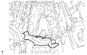
REMOVE FUEL PRESSURE PULSATION DAMPER ASSEMBLY
-
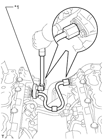
REMOVE NO. 3 FUEL PIPE SUB-ASSEMBLY
-
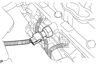
Disconnect the fuel pump connector.
-
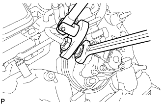
Fix the union bolt on the fuel pump side in place with a 21 mm wrench. Using a 19 mm union nut wrench, loosen the union nut and disconnect the No. 3 fuel pipe sub-assembly from the fuel pump.
Note
Do not loosen the union bolt on the fuel pump side. If the union bolt is accidentally loosened, replace the fuel pump.
-
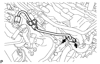
Remove the 2 bolts on the delivery pipe side and remove the No. 3 fuel pipe sub-assembly.
-
Remove the O-ring, backup rings and E-ring from the No. 3 fuel pipe sub-assembly.
-
-
REMOVE NO. 2 FUEL PIPE SUB-ASSEMBLY
Tech Tips
The removal procedures are the same as for the No. 3 fuel pipe sub-assembly.
-
REMOVE NO. 1 ENGINE COVER SUB-ASSEMBLY
-
REMOVE NO. 2 ENGINE COVER SUB-ASSEMBLY
-
REMOVE NO. 2 ENGINE COVER SUB-ASSEMBLY LH
-
REMOVE NO. 4 FUEL PIPE SUB-ASSEMBLY
-
Text in Illustration *1 Union Nut Wrench Using a 19 mm union nut wrench, remove the No. 4 fuel pipe sub-assembly.
-
-
REMOVE FUEL DELIVERY PIPE
-
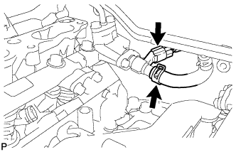
Disconnect the fuel relief valve connector and No. 3 fuel hose.
-
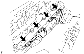
Disconnect the 4 fuel injector connectors.
-
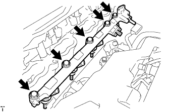
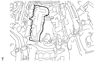
Remove the 5 bolts and fuel delivery pipe from the cylinder head.
Note
-
Be extremely careful not to touch or strike the tips of the fuel injector assemblies.
-
Pull and remove the fuel delivery pipe in a straight line without tilting it.
-
-
Remove the 4 injector vibration insulators from the cylinder head.
-
-
REMOVE NO. 2 FUEL DELIVERY PIPE
-
Disconnect the fuel pressure sensor connector.
-
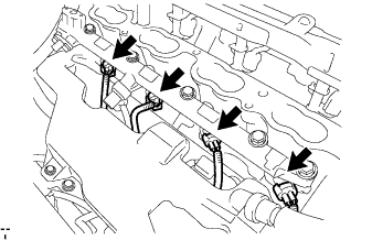
Disconnect the 4 fuel injector connectors.
-
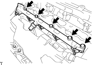
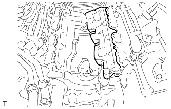
Remove the 5 bolts and No. 2 fuel delivery pipe from the cylinder head.
Note
-
Be extremely careful not to touch or strike the tips of the fuel injector assemblies.
-
Pull and remove the No. 2 fuel delivery pipe in a straight line without tilting it.
-
-
Remove the 4 injector vibration insulators from the cylinder head.
-
-
REMOVE FUEL INJECTOR ASSEMBLY
-
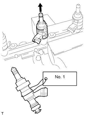
Secure the fuel delivery pipe between aluminum plates in a vise and pull out the fuel injector assembly in a straight line.
Note
-
Do not overtighten the vise.
-
Pull and remove the fuel injector assembly in a straight line to avoid damage to the seal surface of the fuel delivery pipe's O-ring.
-
For reinstallation, attach a tag or label to the fuel injector assembly shaft.
-
-
Remove the nozzle holder clamp from the fuel injector assembly.
-
Remove the O-ring, No. 1 backup ring, No. 2 backup ring, No. 3 backup ring and E-ring from the fuel injector assembly.
-
-
REMOVE FUEL INJECTOR SEAL
-
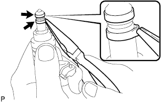
Using the tips of needle-nose pliers, pinch and pull one of the 2 fuel injector seals at several points to stretch it. Repeat this for the other fuel injector seal.
Note
-
Excessively pinching the fuel injector seal may damage the groove of the fuel injector assembly.
-
If a fuel injector assembly is dropped or the tip of the fuel injector assembly is struck, replace it with a new one.
-
-
Remove the 2 fuel injector seals from the fuel injector assembly.
-
-
REMOVE FUEL PIPE SUPPORT SUB-ASSEMBLY
-
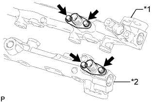
Text in Illustration *1 Fuel Delivery Pipe *2 No. 2 Fuel Delivery Pipe Remove the 4 bolts and 2 fuel pipe support sub-assemblies.
-
Remove the 2 O-rings, 2 No. 1 backup rings, 2 No. 2 backup rings and 2 E-rings from the 2 fuel pipe support sub-assemblies.
-
-
REMOVE FUEL DELIVERY PIPE PLUG
-
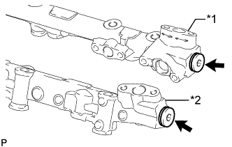
Text in Illustration *1 Fuel Delivery Pipe *2 No. 2 Fuel Delivery Pipe Using a 6 mm hexagon socket wrench, remove the 2 fuel delivery pipe plugs and 2 gaskets from the fuel delivery pipe and No. 2 fuel delivery pipe.
-