POWER DOOR LOCK CONTROL SYSTEM Only Passenger Door LOCK / UNLOCK Functions do not Operate
DESCRIPTION
The front door ECU (for front passenger side) receives lock/unlock switch signals and activates the door lock motor according to these signals.
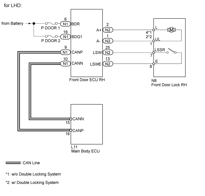
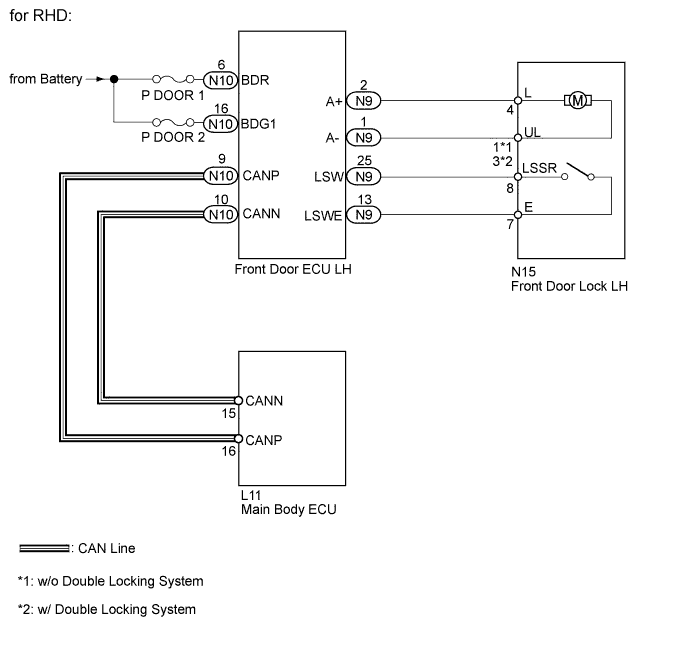
WIRING DIAGRAM
INSPECTION PROCEDURE
PROCEDURE
-
PERFORM ACTIVE TEST USING INTELLIGENT TESTER (FRONT DOOR LOCK)
-
Select the Active Test, use the intelligent tester to generate a control command, and then check the door lock motor function.
Passenger Door (Front door ECU RH*1) (Front door ECU LH*2) Tester Display Test Part Control Range Diagnostic Note Door Lock Operate door lock motor LOCK or UNLOCK - Tech Tips
*1: for LHD
*2: for RHD
OK Front door lock (for front passenger) operates normally.
NG 
INSPECT FUSE (P DOOR 1, P DOOR 2) Click here
OK 
-
-
READ VALUE USING INTELLIGENT TESTER (DOOR LOCK POSITION SWITCH)
-
Use the Data List to check if the door lock position switch is functioning properly.
Passenger Door (Front door ECU RH*1) (Front door ECU LH*2) Tester Display Measurement Item/Range Normal Condition Diagnostic Note Lock Position SW Front passenger side door lock position switch signal/ON or OFF ON: Front passenger side door is unlocked
OFF: Front passenger side door is locked
- Tech Tips
*1: for LHD
*2: for RHD
OK On tester screen, item changes between ON and OFF according to above chart.
NG
INSPECT FRONT DOOR LOCK ASSEMBLY (DOOR LOCK POSITION SWITCH) (for Front Passenger Side) Click here
OK
-
-
CHECK FRONT DOOR ECU (OPERATION) (for Front Passenger Side)
-
Replace the front door ECU (for front passenger) with a normally functioning one Click here.
-
Check that all doors can be locked and unlocked by using the master switch.
OK All doors can be locked and unlocked with master switch.
NG 
REPLACE MAIN BODY ECU
OK 
END (FRONT DOOR ECU IS DEFECTIVE) (for Front Passenger Side)
-
-
INSPECT FUSE (P DOOR 1, P DOOR 2)
-
Remove the P DOOR 1 and P DOOR 2 fuses from the passenger side junction block.
-
Measure the resistance according to the values in the table below.
Standard resistance Tester Connection Condition Specified Condition P DOOR 1 fuse Always Below 1 Ω P DOOR 2 fuse Always Below 1 Ω
NG
REPLACE FUSE
OK
-
-
CHECK HARNESS AND CONNECTOR (FRONT DOOR ECU - BATTERY)
-
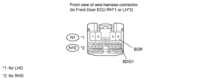
Disconnect the N1 or N10 ECU connector.
-
Measure the voltage according to the value(s) in the table below.
Standard voltage for LHD Tester Connection Condition Specified Condition N1-6 (BDR) - Body ground Always 11 to 14 V N1-16 (BDG1) - Body ground Always 11 to 14 V for RHD Tester Connection Condition Specified Condition N10-6 (BDR) - Body ground Always 11 to 14 V N10-16 (BDG1) - Body ground Always 11 to 14 V
NG
REPAIR OR REPLACE HARNESS OR CONNECTOR
OK
-
-
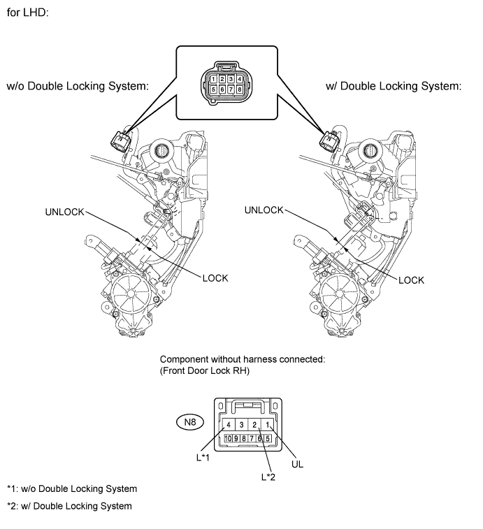
INSPECT FRONT DOOR LOCK ASSEMBLY (for Front Passenger Side)
-
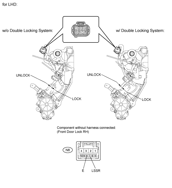
for LHD:
-
Apply battery voltage to the door lock motor and check the operation of the door lock motor.
OK w/o Double Locking System Measurement Condition Specified Condition Battery positive (+) → Terminal 4 (L)
Battery negative (-) → Terminal 1 (UL)
Lock Battery positive (+) → Terminal 1 (UL)
Battery negative (-) → Terminal 4 (L)
Unlock w/ Double Locking System Measurement Condition Specified Condition Battery positive (+) → Terminal 2 (L)
Battery negative (-) → Terminal 1 (UL)
Lock Battery positive (+) → Terminal 1 (UL)
Battery negative (-) → Terminal 2 (L)
Unlock
-
-
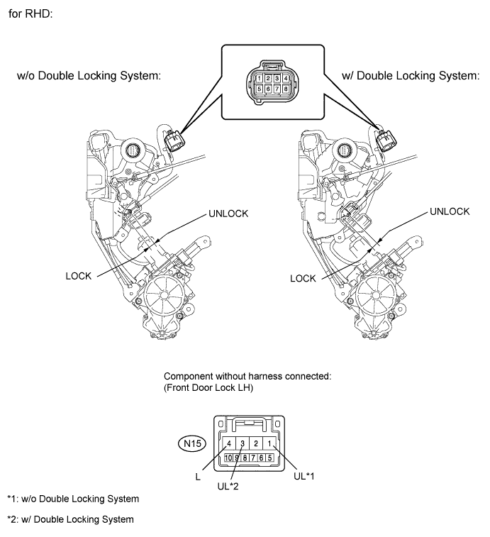
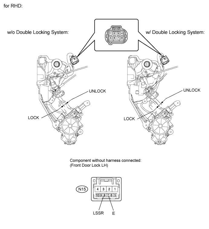
for RHD:
-
Apply battery voltage to the door lock motor and check the operation of the door lock motor.
OK w/o Double Locking System Measurement Condition Specified Condition Battery positive (+) → Terminal 4 (L)
Battery negative (-) → Terminal 1 (UL)
Lock Battery positive (+) → Terminal 1 (UL)
Battery negative (-) → Terminal 4 (L)
Unlock w/ Double Locking System Measurement Condition Specified Condition Battery positive (+) → Terminal 4 (L)
Battery negative (-) → Terminal 3 (UL)
Lock Battery positive (+) → Terminal 3 (UL)
Battery negative (-) → Terminal 4 (L)
Unlock
-
NG
REPLACE FRONT DOOR LOCK ASSEMBLY (for Front Passenger Side) Click here
OK
-
-
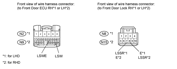
CHECK HARNESS AND CONNECTOR (FRONT DOOR ECU - FRONT DOOR LOCK)
-
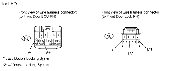
for LHD:
-
Disconnect the N2 ECU connector.
-
Disconnect the N8 door lock connector.
-
Measure the resistance according to the value(s) in the table below.
Standard resistance w/o Double Locking System Tester Connection Condition Specified Connection N2-1 (A-) - N8-1 (UL) Always Below 1 Ω N2-2 (A+) - N8-4 (L) Always Below 1 Ω N8-1 (UL) - Body ground Always 10 kΩ or higher N8-4 (L) - Body ground Always 10 kΩ or higher w/ Double Locking System Tester Connection Condition Specified Connection N2-1 (A-) - N8-1 (UL) Always Below 1 Ω N2-2 (A+) - N8-2 (L) Always Below 1 Ω N8-1 (UL) - Body ground Always 10 kΩ or higher N8-2 (L) - Body ground Always 10 kΩ or higher
-
-
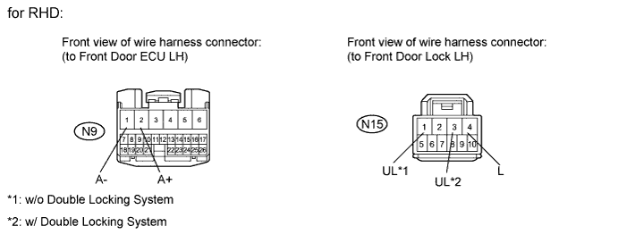
for RHD:
-
Disconnect the N9 ECU connector.
-
Disconnect the N15 door lock connector.
-
Measure the resistance according to the value(s) in the table below.
Standard resistance w/o Double Locking System Tester Connection Condition Specified Connection N15-1 (UL) - N9-1 (A-) Always Below 1 Ω N15-4 (L) - N9-2 (A+) Always Below 1 Ω N9-1 (A-) - Body ground Always 10 kΩ or higher N9-2 (A+) - Body ground Always 10 kΩ or higher w/ Double Locking System Tester Connection Condition Specified Connection N15-1 (UL) - N9-3 (A-) Always Below 1 Ω N15-4 (L) - N9-2 (A+) Always Below 1 Ω N9-3 (A-) - Body ground Always 10 kΩ or higher N9-2 (A+) - Body ground Always 10 kΩ or higher
-
NG
REPAIR OR REPLACE HARNESS OR CONNECTOR
OK
REPLACE FRONT DOOR ECU (for Front Passenger Side) Click here
-
-
INSPECT FRONT DOOR LOCK ASSEMBLY (DOOR LOCK POSITION SWITCH) (for Front Passenger Side)
-
for LHD:
-
Measure the resistance according to the value(s) in the table below.
Standard resistance Tester Connection Switch Condition Specified Condition N8-7 (LSSR) - N8-8 (E) Unlock Below 1 Ω N8-7 (LSSR) - N8-8 (E) Lock 10 kΩ or higher
-
-
for RHD:
-
Measure the resistance according to the value(s) in the table below.
Standard resistance Tester Connection Switch Condition Specified Condition N15-8 (LSSR) - N15-7 (E) Unlock Below 1 Ω N15-8 (LSSR) - N15-7 (E) Lock 10 kΩ or higher
-
NG
REPLACE FRONT DOOR LOCK ASSEMBLY (for Front Passenger Side) Click here
OK
-
-
CHECK HARNESS AND CONNECTOR (FRONT DOOR ECU - FRONT DOOR LOCK)
-
Disconnect the N2 or N9 ECU connector.
-
Disconnect the N8 or N15 door lock connector.
-
Measure the resistance according to the value(s) in the table below.
Standard resistance for LHD Tester Connection Condition Specified Connection N2-13 (LSWE) - N8-8 (E) Always Below 1 Ω N2-25 (LSW) - N8-7 (LSSR) Always Below 1 Ω N2-13 (LSWE) - Body ground Always 10 kΩ or higher N2-25 (LSW) - Body ground Always 10 kΩ or higher for RHD Tester Connection Condition Specified Connection N9-13 (LSWE) - N15-7 (E) Always Below 1 Ω N9-25 (LSW) - N15-8 (LSSR) Always Below 1 Ω N9-13 (LSWE) - Body ground Always 10 kΩ or higher N9-25 (LSW) - Body ground Always 10 kΩ or higher
NG
REPAIR OR REPLACE HARNESS OR CONNECTOR
OK
REPLACE FRONT DOOR ECU (for Front Passenger Side) Click here
-