POWER DOOR LOCK CONTROL SYSTEM TERMINALS OF ECU

-
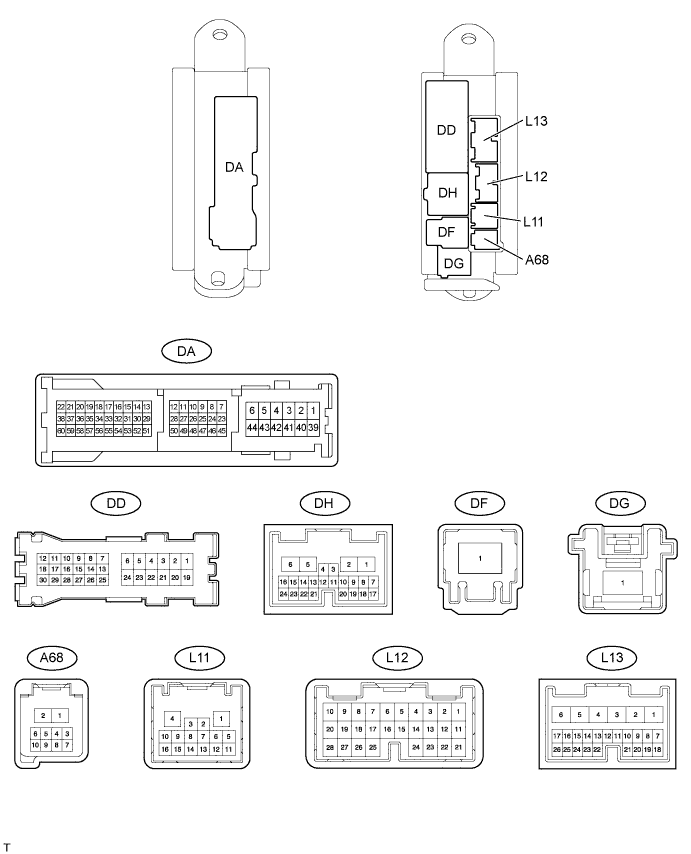
CHECK MAIN BODY ECU (DRIVER SIDE JUNCTION BLOCK)
-
Disconnect the DA, DD, DF, L11, L12, L13 and A68 ECU connectors.
-
Measure the voltage and resistance according to the value(s) in the table below.
Terminal No. (Symbols) Wiring Color Terminal Description Condition Specified Condition L11-1 (GND3) - DA-41 (GND1) W-B - W-B Ground Always Below 1 Ω DA-40 (GND1) - Body ground W-B - Body ground Ground Always Below 1 Ω DA-40 (GND2) - Body ground W-B - Body ground Ground Always Below 1 Ω DF-1 (ALTB) - Body ground B - Body ground IG power supply Always 11 to 14 V L12-1 (AM2) - Body ground W - Body ground Battery power supply Always 11 to 14 V L13-6 (AM1) - Body ground W - Body ground Battery power supply Always 11 to 14 V L13-24 (DCTY) - Body ground W - Body ground Driver side door courtesy light switch input Driver side door is open Below 1 Ω Driver side door is closed 10 kΩ or higher L12-21 (PCTY) - Body ground L - Body ground Front passenger side door courtesy light switch input Front passenger side door is open Below 1 Ω Front passenger side door is closed 10 kΩ or higher L12-7 (RCTY) - Body ground R - Body ground Rear RH side door courtesy light switch input Rear RH side door is open Below 1 Ω Rear RH side door is closed 10 kΩ or higher DD-12 (LCTY) - Body ground L - Body ground Rear LH side door courtesy light switch input Rear LH side door is open Below 1 Ω Rear LH side door is closed 10 kΩ or higher If the result is not as specified, there may be a malfunction on the wire harness side.
-
-
CHECK MASTER SWITCH ASSEMBLY

-
Disconnect the N13 switch connector.
-
Measure the voltage and resistance according to the value(s) in the table below.
Terminal No. (Symbols) Wiring Color Terminal Description Condition Specified Condition N13-12 (GND) - Body ground R - Body ground Ground Always Below 1 Ω N13-11 (B) - N13-12 (GND) B - R Battery power supply Always 11 to 14 V If the result is not as specified, there may be a malfunction on the wire harness side.
-
-
CHECK FRONT DOOR ECU LH

-
Disconnect the N10 ECU connector.
-
Measure the voltage and resistance according to the value(s) in the table below.
Terminal No. (Symbols) Wiring Color Terminal Description Condition Specified Condition N10-1 (GND) - Body ground W-B - Body ground Ground Always Below 1 Ω N10-6 (BDR) - N10-1 (GND) BE - W-B Battery power supply Always 11 to 14 V N10-11 (CPUB) - N10-1 (GND) B*1 - W-B
R*2 - W-B
Battery power supply Always 11 to 14 V N10-16 (BDG1) - N10-1 (GND) R - W-B Battery power supply Always 11 to 14 V Tech Tips
*1: for LHD
*2: for RHD
If the result is not as specified, there may be a malfunction on the wire harness side.
-
Reconnect the N10 ECU connector.
-
Measure the voltage according to the value(s) in the table below.
Terminal No. (Symbols) Wiring Color Terminal Description Condition Specified Condition N9-2 (A+) - N10-1 (GND) R - W-B Door lock motor LOCK drive output Door control switch (master switch or front passenger side door control switch) or driver side door key cylinder UNLOCK 11 to 14 V Door lock motor UNLOCK drive output Door control switch (master switch or front passenger side door control switch) or driver side door key cylinder LOCK Below 1 V N9-1 (A-) - N10-1 (GND) B - W-B Door lock motor UNLOCK drive output Door control switch (master switch or front passenger side door control switch) or driver side door key cylinder UNLOCK 11 to 14 V Door lock motor LOCK drive output Door control switch (master switch or front passenger side door control switch) or driver side door key cylinder LOCK Below 1 V N9-3 (A1+) - N10-1 (GND)*3 GR - W-B Double lock motor SET drive output Double lock SET 11 to 14 V Double lock UNSET Below 1 V N9-4 (A1-) - N10-1 (GND)*3 BE - W-B Double lock motor UNSET drive output Double lock UNSET 11 to 14 V Double lock SET Below 1 V N9-22 (KUL) - N10-1 (GND)*1 GR - W-B Driver side door lock key switch input Driver side door key cylinder UNLOCK Below 1 V Power switch OFF, all doors closed and driver side door key cylinder neutral position Pulse generation
(see waveform 1 or 2)
N9-23 (KL) - N10-1 (GND)*1 P - W-B Driver side door lock key switch input Driver side door key cylinder LOCK Below 1 V Power switch OFF, all doors closed and driver side door key cylinder neutral position Pulse generation
(see waveform 1 or 2)
P10-11 (PML) - P10-20 (DLE)*2 B - W Door control switch (front passenger side door control switch) input Door control switch (front passenger side door control switch) LOCK Below 1 V Power switch OFF, all doors closed and door control switch (front passenger side door control switch) neutral position Pulse generation
(see waveform 3 or 4)
P10-12 (PMUL) - P10-20 (DLE)*2 R - W Door control switch (front passenger side door control switch) input Door control switch (front passenger side door control switch) UNLOCK Below 1 V Power switch OFF, all doors closed and door control switch (front passenger side door control switch) neutral position Pulse generation
(see waveform 3 or 4)
N9-25 (LSW) - N9-13 (LSWE) R - B Driver side door lock position switch input*1
Front passenger side door lock position switch input*2
Driver side door is UNLOCK*1
Front passenger side door is UNLOCK*2
Below 1 V Power switch OFF, all doors closed and driver side door is LOCK*1
Power switch OFF, all doors closed and front passenger side door is LOCK*2
Pulse generation
(see waveform 5 or 6)
N9-20 (DBLS) - N9-21 (DBE)*3 GR - G Double lock position switch signal input Double lock UNSET Below 1 V Power switch OFF, double lock SET Pulse generation
(see waveform 7 or 8)
Tech Tips
*1: for LHD
*2: for RHD
*3: w/ Double locking system
If the result is not as specified, the ECU may have a malfunction.
-
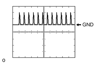
Using an oscilloscope, check waveform 1.
Waveform 1 (Reference): Item Content Terminal No. (Symbols)
-
N9-22 (KUL) - N10-1 (GND)
-
N9-23 (KL) - N10-1 (GND)
Tool Setting 5 V/DIV., 20 ms/DIV. Condition Power switch OFF, all doors closed and driver side door key cylinder neutral position -
-
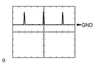
Using an oscilloscope, check waveform 2.
Waveform 2 (Reference): Item Content Terminal No. (Symbols)
-
N9-22 (KUL) - N10-1 (GND)
-
N9-23 (KL) - N10-1 (GND)
Tool Setting 5 V/DIV., 20 ms/DIV. Condition Power switch OFF, all doors closed and driver side door key cylinder neutral position -
-
Using an oscilloscope, check waveform 3.
Waveform 3 (Reference): Item Content Terminal No. (Symbols)
-
P10-12 (PMUL) - N10-1 (GND)
-
P10-11 (PML) - N10-1 (GND)
Tool Setting 5 V/DIV., 20 ms/DIV. Condition Power switch OFF, all doors closed and door control switch (front passenger side door control switch) neutral position -
-
Using an oscilloscope, check waveform 4.
Waveform 4 (Reference): Item Content Terminal No. (Symbols)
-
P10-12 (PMUL) - N10-1 (GND)
-
P10-11 (PML) - N10-1 (GND)
Tool Setting 5 V/DIV., 20 ms/DIV. Condition Power switch OFF, all doors closed and door control switch (front passenger side door control switch) neutral position -
-
Using an oscilloscope, check waveform 5.
Waveform 5 (Reference): Item Content Terminal No. (Symbols) N9-25 (LSW) - N9-13 (LSWE) Tool Setting 5 V/DIV., 20 ms/DIV. Condition Power switch OFF, all doors closed and driver side door is LOCK*1
Power switch OFF, all doors closed and driver side door is LOCK*2
Tech Tips
*1: for LHD
*2: for RHD
-
Using an oscilloscope, check waveform 6.
Waveform 6 (Reference): Item Content Terminal No. (Symbols) N9-25 (LSW) - N9-13 (LSWE) Tool Setting 5 V/DIV., 20 ms/DIV. Condition Power switch OFF, all doors closed and driver side door is LOCK*1
Power switch OFF, all doors closed and driver side door is LOCK*2
Tech Tips
*1: for LHD
*2: for RHD
-
Using an oscilloscope, check waveform 7.
Waveform 7 (Reference): Item Content Terminal No. (Symbols) N9-20 (DBLS) - N9-21 (DBE) Tool Setting 5 V/DIV., 20 ms/DIV. Condition Power switch OFF, double lock SET -
Using an oscilloscope, check waveform 8.
Waveform 8 (Reference): Item Content Terminal No. (Symbols) N9-20 (DBLS) - N9-21 (DBE) Tool Setting 5 V/DIV., 20 ms/DIV. Condition Power switch OFF, double lock SET
-
-
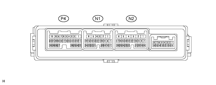
CHECK FRONT DOOR ECU RH
-
Disconnect the N1 ECU connector.
-
Measure the voltage and resistance according to the value(s) in the table below.
Terminal No. (Symbols) Wiring Color Terminal Description Condition Specified Condition N1-1 (GND) - Body ground W-B - Body ground Ground Always Below 1 Ω N1-6 (BDR) - N1-1 (GND) BE - W-B Battery power supply Always 11 to 14 V N1-11 (CPUB) - N1-1 (GND) R*1 - W-B
B*2 - W-B
Battery power supply Always 11 to 14 V N1-16 (BDG1) - N1-1 (GND) R - W-B Battery power supply Always 11 to 14 V Tech Tips
*1: for LHD
*2: for RHD
If the result is not as specified, there may be a malfunction on the wire harness side.
-
Reconnect the N1 ECU connector.
-
Measure the voltage according to the value(s) in the table below.
Terminal No. (Symbols) Wiring Color Terminal Description Condition Specified Condition N2-2 (A+) - N1-1 (GND) R - W-B Door lock motor LOCK drive output Door control switch (master switch or front passenger side door control switch) or driver side door key cylinder UNLOCK 11 to 14 V Door lock motor UNLOCK drive output Door control switch (master switch or front passenger side door control switch) or driver side door key cylinder LOCK Below 1 V N2-1 (A-) - N1-1 (GND) B - W-B Door lock motor UNLOCK drive output Door control switch (master switch or front passenger side door control switch) or driver side door key cylinder UNLOCK 11 to 14 V Door lock motor LOCK drive output Door control switch (master switch or front passenger side door control switch) or driver side door key cylinder LOCK Below 1 V N2-3 (A1+) - N1-1 (GND)*3 GR - W-B Double lock motor SET drive output Double lock SET 11 to 14 V Double lock UNSET Below 1 V N2-4 (A1-) - N1-1 (GND)*3 BE - W-B Double lock motor UNSET drive output Double lock UNSET 11 to 14 V Double lock SET Below 1 V N2-22 (KUL) - N1-1 (GND)*1 GR - W-B Driver side door lock key switch input Driver side door key cylinder UNLOCK Below 1 V Power switch OFF, all doors closed and driver side door key cylinder neutral position Pulse generation
(see waveform 1 or 2)
N2-23 (KL) - N1-1 (GND)*1 P - W-B Driver side door lock key switch input Driver side door key cylinder LOCK Below 1 V Power switch OFF, all doors closed and driver side door key cylinder neutral position Pulse generation
(see waveform 1 or 2)
P4-11 (PML) - P4-20 (DLE)*2 B - W Door control switch (front passenger side door control switch) input Door control switch (front passenger side door control switch) LOCK Below 1 V Power switch OFF, all doors closed and door control switch (front passenger side door control switch) neutral position Pulse generation
(see waveform 3 or 4)
P4-12 (PMUL) - P4-20 (DLE)*2 R - W Door control switch (front passenger side door control switch) input Door control switch (front passenger side door control switch) UNLOCK Below 1 V Power switch OFF, all doors closed and door control switch (front passenger side door control switch) neutral position Pulse generation
(see waveform 3 or 4)
N2-25 (LSW) - N2-13 (LSWE) R - B Driver side door lock position switch input*1
Front passenger side door lock position switch input*2
Driver side door is UNLOCK*1
Front passenger side door is UNLOCK*2
Below 1 V Power switch OFF, all doors closed and driver side door is LOCK*1
Power switch OFF, all doors closed and front passenger side door is LOCK*2
Pulse generation
(see waveform 5 or 6)
N2-20 (DBLS) - N2-21 (DBE)*3 GR - G Double lock position switch signal input Double lock UNSET Below 1 V Power switch OFF, double lock SET Pulse generation
(see waveform 7 or 8)
Tech Tips
*1: for RHD
*2: for LHD
*3: w/ Double Locking System
If the result is not as specified, the ECU may have a malfunction.
-
Using an oscilloscope, check waveform 1.
Waveform 1 (Reference): Item Content Terminal No. (Symbols)
-
N2-22 (KUL) - N1-1 (GND)
-
N2-23 (KL) - N1-1 (GND)
Tool Setting 5 V/DIV., 20 ms/DIV. Condition Power switch OFF, all doors closed and driver side door key cylinder neutral position -
-
Using an oscilloscope, check waveform 2.
Waveform 2 (Reference): Item Content Terminal No. (Symbols)
-
N2-22 (KUL) - N1-1 (GND)
-
N2-23 (KL) - N1-1 (GND)
Tool Setting 5 V/DIV., 20 ms/DIV. Condition Power switch OFF, all doors closed and driver side door key cylinder neutral position -
-
Using an oscilloscope, check waveform 3.
Waveform 3 (Reference): Item Content Terminal No. (Symbols)
-
P4-12 (PMUL) - N1-1 (GND)
-
P4-11 (PML) - N1-1 (GND)
Tool Setting 5 V/DIV., 20 ms/DIV. Condition Power switch OFF, all doors closed and door control switch (front passenger side door control switch) neutral position -
-
Using an oscilloscope, check waveform 4.
Waveform 4 (Reference): Item Content Terminal No. (Symbols)
-
P4-12 (PMUL) - N1-1 (GND)
-
P4-11 (PML) - N1-1 (GND)
Tool Setting 5 V/DIV., 20 ms/DIV. Condition Power switch OFF, all doors closed and door control switch (front passenger side door control switch) neutral position -
-
Using an oscilloscope, check waveform 5.
Waveform 5 (Reference): Item Content Terminal No. (Symbols) N2-25 (LSW) - N2-13 (LSWE) Tool Setting 5 V/DIV., 20 ms/DIV. Condition Power switch OFF, all doors closed and driver side door is LOCK*1
Power switch OFF, all doors closed and front passenger side door is LOCK*2
Tech Tips
*1: for RHD
*2: for LHD
-
Using an oscilloscope, check waveform 6.
Waveform 6 (Reference): Item Content Terminal No. (Symbols) N2-25 (LSW) - N2-13 (LSWE) Tool Setting 5 V/DIV., 20 ms/DIV. Condition Power switch OFF, all doors closed and driver side door is LOCK*1
Power switch OFF, all doors closed and front passenger side door is LOCK*2
Tech Tips
*1: for RHD
*2: for LHD
-
Using an oscilloscope, check waveform 7.
Waveform 7 (Reference): Item Content Terminal No. (Symbols) N2-20 (DBLS) - N2-21 (DBE) Tool Setting 5 V/DIV., 20 ms/DIV. Condition Power switch OFF, double lock SET -
Using an oscilloscope, check waveform 8.
Waveform 8 (Reference): Item Content Terminal No. (Symbols) N2-20 (DBLS) - N2-21 (DBE) Tool Setting 5 V/DIV., 20 ms/DIV. Condition Power switch OFF, double lock SET
-
-
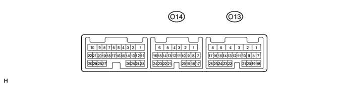
CHECK REAR DOOR ECU LH
-
Disconnect the O14 ECU connector.
-
Measure the voltage and resistance according to the value(s) in the table below.
Terminal No. (Symbols) Wiring Color Terminal Description Condition Specified Condition O14-1 (GND) - Body ground W-B - Body ground Ground Always Below 1 Ω O14-6 (BDR) - O14-1 (GND) L - W-B Battery power supply Always 11 to 14 V O14-11 (CPUB) - O14-1 (GND) R - W-B Battery power supply Always 11 to 14 V If the result is not as specified, there may be a malfunction on the wire harness side.
-
Reconnect the O14 ECU connector.
-
Measure the voltage according to the value(s) in the table below.
Terminal No. (Symbols) Wiring Color Terminal Description Condition Specified Condition O13-2 (A+) - O14-1 (GND) R - W-B Door lock motor LOCK drive output Door control switch (master switch or front passenger side door control switch) or driver side door key cylinder UNLOCK 11 to 14 V Door lock motor UNLOCK drive output Door control switch (master switch or front passenger side door control switch) or driver side door key cylinder LOCK Below 1 V O13-1 (A-) - O14-1 (GND) B - W-B Door lock motor UNLOCK drive output Door control switch (master switch or front passenger side door control switch) or driver side door key cylinder UNLOCK 11 to 14 V Door lock motor LOCK drive output Door control switch (master switch or front passenger side door control switch) or driver side door key cylinder LOCK Below 1 V O13-10 (A1+) - O14-1 (GND)* BE - W-B Double lock motor SET drive output Double lock SET 11 to 14 V Double lock UNSET Below 1 V O13-11 (A1-) - O14-1 (GND)* GR - W-B Double lock motor UNSET drive output Double lock UNSET 11 to 14 V Double lock SET Below 1 V O13-14 (LSW) - O13-23 (LSWE) R - B Rear LH side door lock position switch input Rear LH side door is UNLOCK Below 1 V Power switch OFF, all doors closed and rear LH side door is LOCK Pulse generation
(see waveform 1 or 2)
O13-18 (DBLS) - O13-19 (DLE1)* GR - BE Double lock position switch signal input Double lock UNSET Below 1 V Power switch OFF, double lock SET Pulse generation
(see waveform 3 or 4)
Tech Tips
*: w/ Double Locking System
If the result is not as specified, the ECU may have a malfunction.
-
Using an oscilloscope, check waveform 1.
Waveform 1 (Reference): Item Content Terminal No. (Symbols) O13-14 (LSW) - O13-23 (LSWE) Tool Setting 5 V/DIV., 20 ms/DIV. Condition Power switch OFF, all doors closed and rear LH side door is LOCK -
Using an oscilloscope, check waveform 2.
Waveform 2 (Reference): Item Content Terminal No. (Symbols) O13-14 (LSW) - O13-23 (LSWE) Tool Setting 5 V/DIV., 20 ms/DIV. Condition Power switch OFF, all doors closed and rear LH side door is LOCK -
Using an oscilloscope, check waveform 3.
Waveform 3 (Reference): Item Content Terminal No. (Symbols) O13-18 (DBLS) - O13-19 (DLE1) Tool Setting 5 V/DIV., 20 ms/DIV. Condition Power switch OFF, double lock SET -
Using an oscilloscope, check waveform 4.
Waveform 4 (Reference): Item Content Terminal No. (Symbols) O13-18 (DBLS) - O13-19 (DLE1) Tool Setting 5 V/DIV., 20 ms/DIV. Condition Power switch OFF, double lock SET
-
-
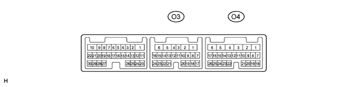
CHECK REAR DOOR ECU RH
-
Disconnect the O3 ECU connector.
-
Measure the voltage and resistance according to the value(s) in the table below.
Terminal No. (Symbols) Wiring Color Terminal Description Condition Specified Condition O3-1 (GND) - Body ground W-B - Body ground Ground Always Below 1 Ω O3-6 (BDR) - O3-1 (GND) L - W-B Battery power supply Always 11 to 14 V O3-11 (CPUB) - O3-1 (GND) R - W-B Battery power supply Always 11 to 14 V If the result is not as specified, there may be a malfunction on the wire harness side.
-
Reconnect the O3 ECU connector.
-
Measure the voltage according to the value(s) in the table below.
Terminal No. (Symbols) Wiring Color Terminal Description Condition Specified Condition O4-2 (A+) - O3-1 (GND) R - W-B Door lock motor LOCK drive output Door control switch (master switch or front passenger side door control switch) or driver side door key cylinder UNLOCK 11 to 14 V Door lock motor UNLOCK drive output Door control switch (master switch or front passenger side door control switch) or driver side door key cylinder LOCK Below 1 V O4-1 (A-) - O3-1 (GND) B - W-B Door lock motor UNLOCK drive output Door control switch (master switch or front passenger side door control switch) or driver side door key cylinder UNLOCK 11 to 14 V Door lock motor LOCK drive output Door control switch (master switch or front passenger side door control switch) or driver side door key cylinder LOCK Below 1 V O4-10 (A1+) - O3-1 (GND)* GR - W-B Double lock motor SET drive output Double lock SET 11 to 14 V Double lock UNSET Below 1 V O4-11 (A1-) - O3-1 (GND)* BE - W-B Double lock motor UNSET drive output Double lock UNSET 11 to 14 V Double lock SET Below 1 V O4-14 (LSW) - O4-23 (LSWE) R - B Rear RH side door lock position switch input Rear RH side door is UNLOCK Below 1 V Rear RH side door lock position switch input Power switch OFF, all doors closed and rear RH side door is LOCK Pulse generation
(see waveform 1 or 2)
O4-18 (DBLS) - O4-19 (DLE1)* GR - BE Double lock position switch signal input Double lock UNSET Below 1 V Power switch OFF, double lock SET Pulse generation
(see waveform 3 or 4)
Tech Tips
*: w/ Double Locking System
If the result is not as specified, the ECU may have a malfunction.
-
Using an oscilloscope, check waveform 1.
Waveform 1 (Reference): Item Content Terminal No. (Symbols) O4-14 (LSW) - O4-23 (LSWE) Tool Setting 5 V/DIV., 20 ms/DIV. Condition Power switch OFF, all doors closed and rear RH side door is LOCK -
Using an oscilloscope, check waveform 2.
Waveform 2 (Reference): Item Content Terminal No. (Symbols) O4-14 (LSW) - O4-23 (LSWE) Tool Setting 5 V/DIV., 20 ms/DIV. Condition Power switch OFF, all doors closed and rear RH side door is LOCK -
Using an oscilloscope, check waveform 3.
Waveform 3 (Reference): Item Content Terminal No. (Symbols) O4-18 (DBLS) - O4-19 (DLE1) Tool Setting 5 V/DIV., 20 ms/DIV. Condition Power switch OFF, double lock SET -
Using an oscilloscope, check waveform 4.
Waveform 4 (Reference): Item Content Terminal No. (Symbols) O4-18 (DBLS) - O4-19 (DLE1) Tool Setting 5 V/DIV., 20 ms/DIV. Condition Power switch OFF, double lock SET
-