FRONT WIPER MOTOR INSTALLATION

Tech Tips
-
Use the same procedure for RHD and LHD vehicles.
-
The procedure listed below is for LHD vehicles.
-
INSTALL WINDSHIELD WIPER MOTOR ASSEMBLY
-
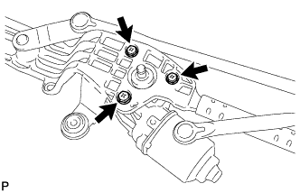
Install the windshield wiper motor assembly with the 3 bolts.
- Torque:
- 5.5 N*m { 56 kgf*cm, 49 in.*lbf }
-
-
INSTALL FRONT WIPER CRANK SUB-ASSEMBLY
-
Check the automatic stop position.
-
Check that the motor stops automatically at the automatic stop position Click here.
-
-
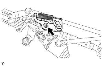
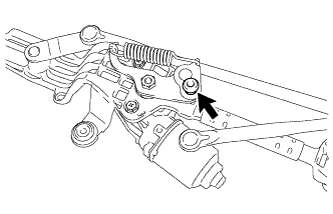
Temporarily install the front wiper crank sub-assembly to the windshield wiper motor assembly with the nut.
-
Temporarily install the wiper link to the front wiper crank pivot.
-
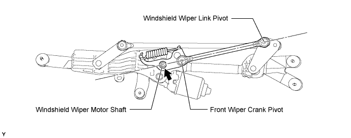
Align the front wiper crank sub-assembly with the wiper link as shown in the illustration.
-
Tighten the front wiper crank sub-assembly nut.
- Torque:
- 17 N*m { 175 kgf*cm, 13 ft.*lbf }
-
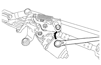
Apply MP grease to the front wiper crank pivot of the front wiper crank sub-assembly.
-
Install the wiper link to the front wiper crank pivot.
-
-
INSTALL WIPER MOTOR COVER
-
Attach the wiper motor cover.
-
-
INSTALL WINDSHIELD WIPER LINK ASSEMBLY
-
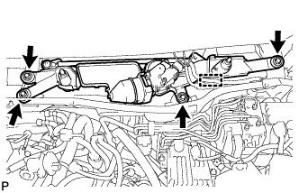
Install the wiper motor and link assembly with the 4 bolts.
- Torque:
- 5.5 N*m { 56 kgf*cm, 49 in.*lbf }
-
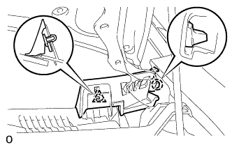
Connect the connector. Then attach the clamp to install the wire harness to the cowl top panel.
-
-
INSTALL COWL TOP VENTILATOR LOUVER SUB-ASSEMBLY
-
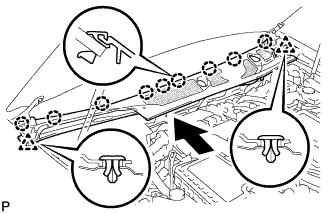
Push the ventilator louver in the direction indicated by the arrow in the illustration to attach the 9 claws and 2 clips and install the ventilator louver.
-
-
INSTALL COWL TOP VENTILATOR LOUVER PROTECTOR RH
-
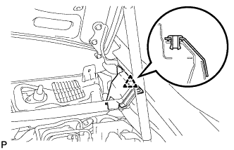
Attach the claw and guide to install the cowl top ventilator louver protector LH.
-
Attach the clip.
-
-
INSTALL FRONT FENDER TO COWL SIDE SEAL LH
-
Attach the claw and clip to install the front fender to cowl side seal LH.
-
-
INSTALL FRONT FENDER TO COWL SIDE SEAL RH
Tech Tips
Use the same procedure described for the LH side.
-
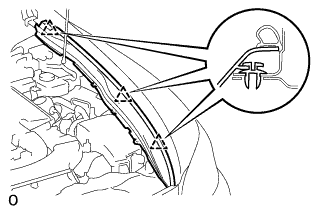
INSTALL COWL TOP VENTILATOR LOUVER RH
-
Install the cowl top ventilator louver RH with the 6 clips.
Note
Be sure to install the cowl top ventilator louver RH properly. If it is not installed properly, water may enter the engine room and cause malfunctions.
-
-
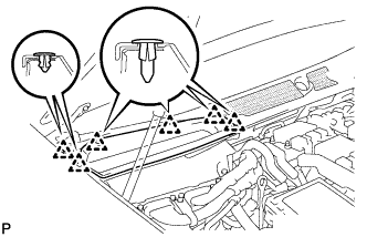
INSTALL HOOD TO COWL TOP SEAL
-
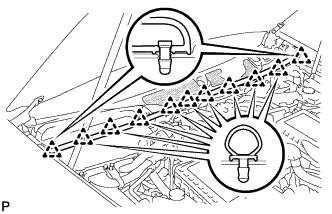
Attach the 11 clips to install the cowl top seal.
-
-
INSTALL FRONT UPPER FENDER PROTECTOR LH
-
Attach the clips to install the upper fender protector.
-
-
INSTALL FRONT UPPER FENDER PROTECTOR RH
Tech Tips
Use the same procedure described for the LH side.
-
INSTALL ENGINE ROOM SIDE COVER LH
-
Install the engine room side cover LH with the 5 clips.
-
-
INSTALL ENGINE ROOM SIDE COVER RH
-
Install the engine room side cover RH with the 5 clips.
-
-
CONNECT CABLE TO AUXILIARY BATTERY NEGATIVE TERMINAL
Note
When disconnecting the cable, some systems need to be initialized after the cable is reconnected Click here.
-
INSTALL FRONT WIPER ARM LH
-
Stop the wiper motor at the automatic stop position.
-
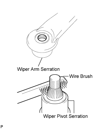
Clean the wiper arm serration with a round file or equivalent.
-
Clean the wiper pivot serration with a wire brush.
-
Install the wiper arm and blade with the nut. Make sure that the wiper arm and blade comes to the position shown in the illustration.
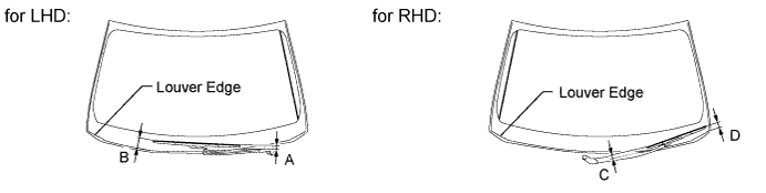
Standard measurement Position Specified Condition A 16.3 mm (0.646 in.) B 61.7 to 76.7 mm (2.43 to 3.02 in.) C 23.2 mm (0.913 in.) D 35.6 to 50.6 mm (1.40 to 1.99 in.) - Torque:
- 22 N*m { 224 kgf*cm, 16 ft.*lbf }
Tech Tips
Hold down the wiper arm hinge with your hand while tightening the nut.
-
-
INSTALL FRONT WIPER ARM RH
-
Stop the wiper motor at the automatic stop position.
-
Clean the wiper arm serration with a round file or equivalent.
-
Clean the wiper pivot serration with a wire brush.
-
Install the wiper arm and blade with the nut. Make sure that the wiper arm and blade comes to the position shown in the illustration.
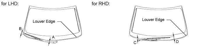
Standard measurement Position Specified Condition A 23.2 mm (0.913 in.) B 35.6 to 50.6 mm (1.40 to 1.99 in.) C 16.3 mm (0.646 in.) D 61.7 to 76.7 mm (2.43 to 3.02 in.) - Torque:
- 22 N*m { 224 kgf*cm, 16 ft.*lbf }
Tech Tips
Hold down the wiper arm hinge with your hand while tightening the nut.
-
Operate the front wipers while spraying washer fluid on the windshield glass. Make sure that the front wipers function properly and there is no interference with the vehicle body.
-
-
INSTALL BATTERY SERVICE HOLE COVER LH
-

Text in Illustration *A for Standard *B for Ottoman Attach the battery service hole cover LH with the clip and fastening tape.
-
-
INSTALL DECK TRIM SIDE BOARD LH (w/o Spare Tire)
-

Attach the 2 clips to install the deck trim side board LH.
-
-
INSTALL DECK BOARD ASSEMBLY (w/o Spare Tire)

-
INSTALL LUGGAGE COMPARTMENT MAT SUB-ASSEMBLY (w/ Spare Tire)
