WIPER AND WASHER SYSTEM Washer Fluid Level Warning Switch Circuit
DESCRIPTION
The front controller receives washer fluid level warning switch information, and sends it through CAN line to the combination meter. The combination meter receives this information, and turns on the washer fluid level warning switch when the washer fluid becomes low.
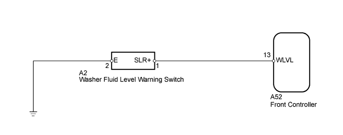
WIRING DIAGRAM
INSPECTION PROCEDURE
PROCEDURE
-
READ VALUE USING INTELLIGENT TESTER (WASHER FLUID LEVEL WARNING SWITCH)
-
Check the Data List for proper functioning of the washer fluid level warning switch.
Body No. 5: Tester Display Measurement Item / Range Normal Condition Diagnostic Note Washer Level Switch Washer fluid level warning switch / ON or OFF ON: Washer jar and tank is empty
OFF: Washer jar and tank is full
- OK The display is as specified in the normal condition.
NG 
INSPECT WASHER FLUID LEVEL WARNING SWITCH Click here
OK 
PROCEED TO NEXT CIRCUIT INSPECTION SHOWN IN PROBLEM SYMPTOMS TABLE Click here
-
-
INSPECT WASHER FLUID LEVEL WARNING SWITCH
-
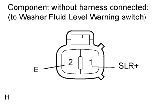
Disconnect the A2 switch connector.
-
Measure the resistance according to the value(s) in the table below.
Standard resistance Tester Connection Condition Specified Condition 1 (SLR+) - 2 (E) Washer jar and tank is empty Below 1 Ω 1 (SLR+) - 2 (E) Washer jar and tank is full 10 kΩ or higher
NG 
REPLACE WASHER FLUID LEVEL WARNING SWITCH Click here
OK 
-
-
CHECK HARNESS AND CONNECTOR (WARNING SWITCH - FRONT CONTROLLER AND BODY GROUND)
-
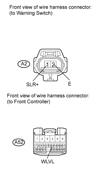
Disconnect the A2 switch connector.
-
Disconnect the A52 Front controller connector.
-
Measure the resistance according to the value(s) in the table below.
Standard resistance Tester Connection Condition Specified Condition A2-1 (SLR+) - A52-13 (WLVL) Always Below 1 Ω A2-2 (E) - Body ground A2-1 (SLR+) - Body ground Always 10 kΩ or higher
NG
REPAIR OR REPLACE HARNESS OR CONNECTOR
OK
REPLACE FRONT CONTROLLER
-