WIPER AND WASHER SYSTEM Front Wiper Motor Circuit
DESCRIPTION
The front controller controls the wiper motor.
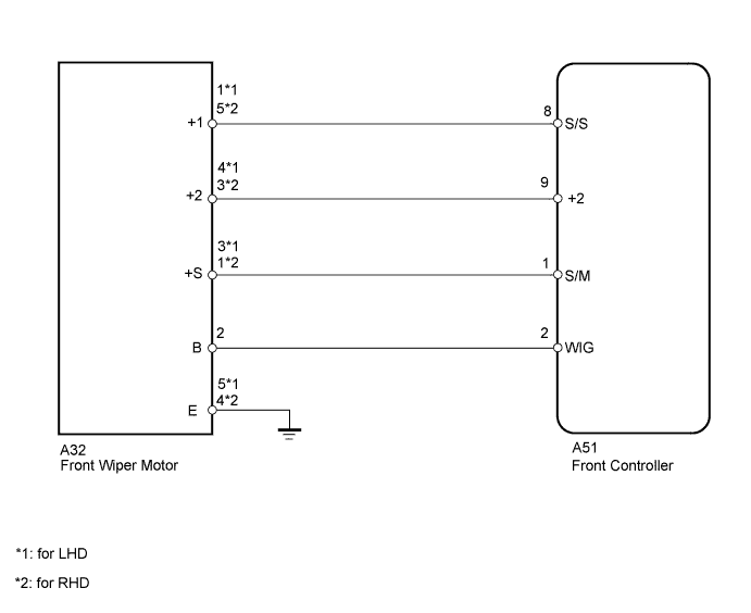
WIRING DIAGRAM
INSPECTION PROCEDURE
PROCEDURE
-
PERFORM ACTIVE TEST USING INTELLIGENT TESTER (FRONT WIPER MOTOR)
-
Select the Active Test, use the intelligent tester to generate a control command, and then check the front wiper motor.
Note
When a Body No. 5 (front controller) related vehicle switch is ON, Active Test items related to the vehicle switch are prohibited (double operation prohibition). Check that the vehicle switches are OFF before performing Active Test.
Body No. 5: Item Test Details Control Range Diagnostic Note Wiper Mot (HI) Front wiper motor HI operation ON / OFF - Wiper Mot (LO) Front wiper motor LO operation ON / OFF - OK Front wiper motor operates.
NG 
INSPECT FRONT WIPER MOTOR Click here
OK 
PROCEED TO NEXT CIRCUIT INSPECTION SHOWN IN PROBLEM SYMPTOMS TABLE Click here
-
-
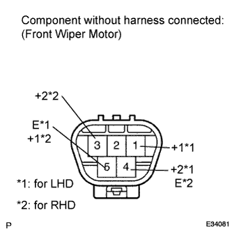
INSPECT FRONT WIPER MOTOR
-
Remove the front wiper motor Click here.
-
Apply battery voltage to the front wiper motor and check the speed of the front wiper motor.
OK for LHD Measurement Condition Specified Condition Battery positive (+) → Terminal 1 (+1)
Battery negative (-) → Terminal 5 (E)
Motor operates at low speed Battery positive (+) → Terminal 4 (+2)
Battery negative (-) → Terminal 5 (E)
Motor operates at high speed -
Apply battery voltage to the front wiper motor and check the speed of the front wiper motor.
OK for RHD Measurement Condition Specified Condition Battery positive (+) → Terminal 5 (+1)
Battery negative (-) → Terminal 4 (E)
Motor operates at low speed Battery positive (+) → Terminal 3 (+2)
Battery negative (-) → Terminal 4 (E)
Motor operates at high speed
NG 
REPLACE FRONT WIPER MOTOR Click here
OK 
-
-
CHECK HARNESS AND CONNECTOR (FRONT WIPER MOTOR - FRONT CONTROLLER AND BODY GROUND)
-
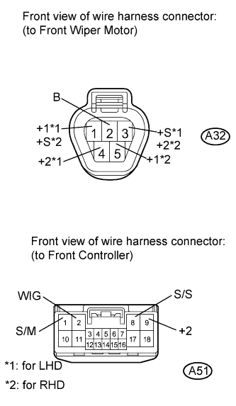
Disconnect the A32 motor connector.
-
Disconnect the A51 ECU connector.
-
Measure the resistance according to the value(s) in the table below.
Standard resistance for LHD: Tester Connection Condition Specified Condition A32-2 (B) - A51-2 (WIG) Always Below 1 Ω A32-1 (+1) - A51-8 (S/S) A32-4 (+2) - A51-9 (+2) A32-3 (+S) - A51-1 (S/M) A32-5 (E) - Body ground A32-3 (+S) - Body ground Always 10 kΩ or higher A32-2 (B) - Body ground A32-4 (+2) - Body ground A32-1 (+1) - Body ground for RHD: Tester Connection Condition Specified Condition A32-2 (B) - A51-2 (WIG) Always Below 1 Ω A32-5 (+1) - A51-8 (S/S) A32-3 (+2) - A51-9 (+2) A32-1 (+S) - A51-1 (S/M) A32-4 (E) - Body ground A32-1 (+S) - Body ground Always 10 kΩ or higher A32-2 (B) - Body ground A32-3 (+2) - Body ground A32-5 (+1) - Body ground
NG
REPAIR OR REPLACE HARNESS OR CONNECTOR
OK
REPLACE FRONT CONTROLLER
-