STOP LIGHT SWITCH INSTALLATION

Tech Tips
-
Use the same procedure for RHD and LHD vehicles.
-
The procedure listed below is for LHD vehicles.
-
INSTALL STOP LIGHT SWITCH ASSEMBLY
-
Temporarily install the stop light switch assembly with the lock nut.
Tech Tips
Tighten the stop light switch assembly with the lock nut after inspecting and adjusting the brake pedal height.
-
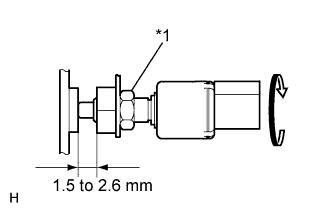
Text in Illustration *1 Lock Nut Turn the stop light switch assembly so that its protrusion is between 1.5 and 2.6 mm (0.059 and 0.102 in.). Then tighten the lock nut.
- Torque:
- 17 N*m { 170 kgf*cm, 12 ft.*lbf }
-
Connect the connector.
-
Without depressing the brake pedal, check that the stop light does not illuminate. If it illuminates, adjust the brake pedal height again.
-
Push the brake pedal in 5 to 10 mm (0.20 to 0.39 in.), and check that the stop light turns on. If the stop light does not turn on, adjust the brake pedal height again.
-
-
INSTALL NO. 1 INSTRUMENT PANEL UNDER COVER SUB-ASSEMBLY
-
Connect the connector.
-
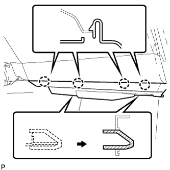
Insert the 2 guides.
-
Attach the 4 claws to install the No. 2 instrument panel under cover sub-assembly.
-