INTERIOR ILLUMINATION LIGHT REMOVAL

Tech Tips
-
Use the same procedure for RHD and LHD vehicles.
-
The procedure listed below is for LHD vehicles.
-
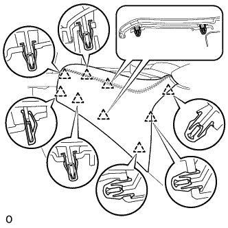
REMOVE INSTRUMENT PANEL FINISH PANEL END LH
-
Pull the front part of the instrument panel finish panel end LH to detach the 6 clips.
-
Pull the instrument panel finish panel end LH to detach 3 clips and remove the instrument panel finish panel end LH.
-
-
REMOVE INSTRUMENT PANEL FINISH PANEL END RH
Tech Tips
Use the same procedure described for the LH side.
-
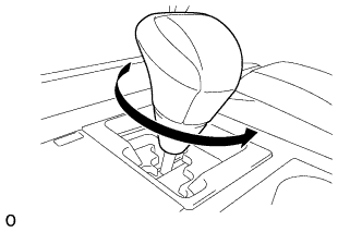
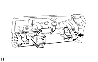
REMOVE SHIFT LEVER KNOB SUB-ASSEMBLY
-
Twist the shift lever knob sub-assembly in the direction indicated by the arrow and remove it.
-
-
REMOVE UPPER INSTRUMENT CLUSTER FINISH PANEL
-
Disconnect the connector.
-
Detach the 6 clips and remove the upper console panel sub-assembly.
-
-
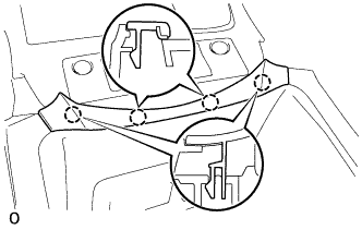
REMOVE NO. 3 BOX PANEL
-
Detach the 4 claws and remove the No. 3 box panel.
-
-
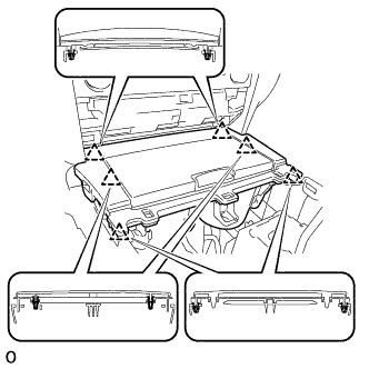
REMOVE UPPER REAR CONSOLE PANEL SUB-ASSEMBLY
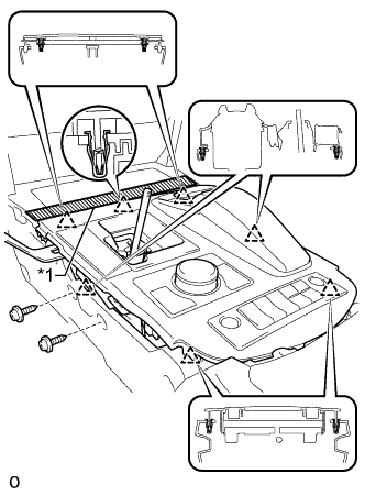
Text in Illustration *1 Protective Tape
-
Apply protective tape as shown in the illustration.
-
Move the shift lever to N.
-
Remove the 2 screws.
-
Detach the 6 clips and remove the upper rear console panel sub-assembly.
-
Disconnect each connector and detach each wire harness clamp.
-
-
REMOVE UPPER CONSOLE PANEL SUB-ASSEMBLY
-
Disconnect the connector.
-
Detach the 6 clips and remove the upper console panel sub-assembly.
-
-
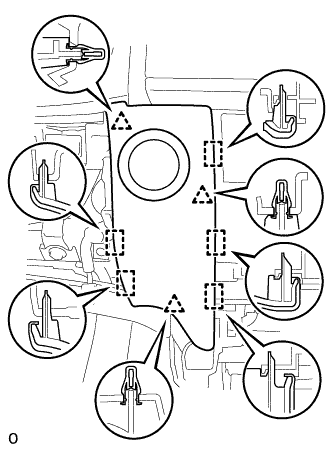
REMOVE LOWER NO. 1 INSTRUMENT PANEL FINISH PANEL
-
Detach the 4 clips and 5 guides and remove the lower No. 1 instrument panel finish panel.
-
Disconnect the connector.
-
-
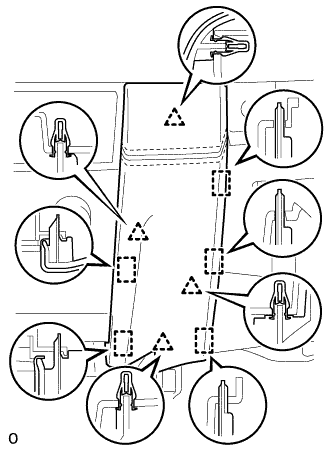
REMOVE LOWER NO. 2 INSTRUMENT PANEL FINISH PANEL
-
Detach the 4 clips and 5 guides and remove the lower No. 2 instrument panel finish panel.
-
-
REMOVE MULTI-MEDIA MODULE RECEIVER ASSEMBLY
-
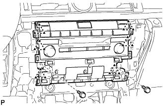
Remove the 2 bolts.
-
Detach the 6 clips and pull out the multi-media module receiver assembly with bracket.
-
Disconnect the connectors and remove the multimedia module receiver assembly with bracket.
-
-
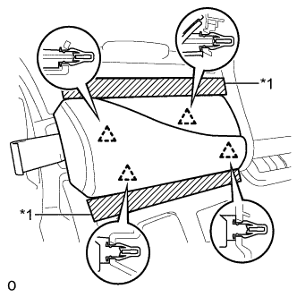
REMOVE INSTRUMENT SIDE PANEL RH
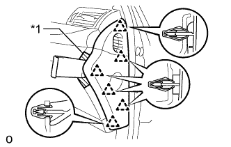
Text in Illustration *1 Protective Tape
-
Apply protective tape as shown in the illustration.
-
Using moulding remover D, detach the 6 clips and remove the instrument side panel RH.
-
-
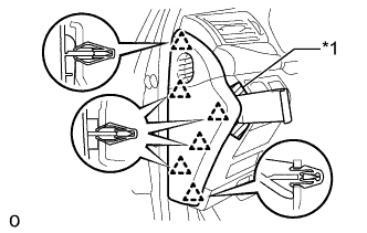
REMOVE INSTRUMENT CLUSTER FINISH PANEL GARNISH ASSEMBLY
-
Apply protective tape as shown in the illustration.
-
Using moulding remover B, detach the 12 clips and remove the instrument cluster finish panel garnish assembly.
-
Disconnect each connector.
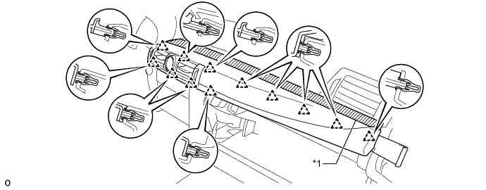
Text in Illustration *1 Protective Tape - -
-
-
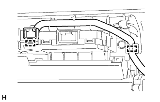
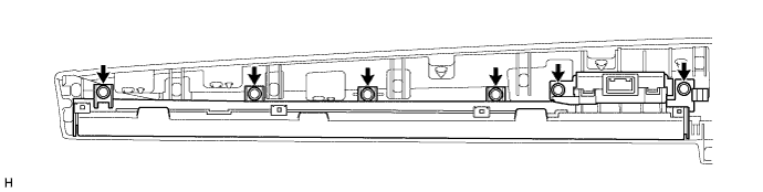
REMOVE NO. 1 INSTRUMENT PANEL GARNISH SUB-ASSEMBLY (INTERIOR ILLUMINATION LIGHT)
-
Detach the 2 clamps.
-
Remove the 6 screws and No. 1 instrument panel garnish sub-assembly (interior illumination light).
-
-
REMOVE INSTRUMENT SIDE PANEL LH
Text in Illustration *1 Protective Tape
-
Apply protective tape as shown in the illustration.
-
Using moulding remover D, detach the 6 clips and remove the instrument side panel LH.
-
-
REMOVE INSTRUMENT PANEL ORNAMENT
Text in Illustration *1 Protective Tape
-
Apply protective tape as shown in the illustration.
-
Using moulding remover B, detach the 4 clips and remove the instrument panel ornament.
-
Disconnect the connector.
-
-
REMOVE NO. 2 INSTRUMENT PANEL GARNISH SUB-ASSEMBLY (INTERIOR ILLUMINATION LIGHT)
-
Remove the screw.
-
Detach the guide to remove the No. 2 instrument panel garnish sub-assembly (interior illumination light).
-