LIGHTING SYSTEM Front Fog Light does not Illuminate
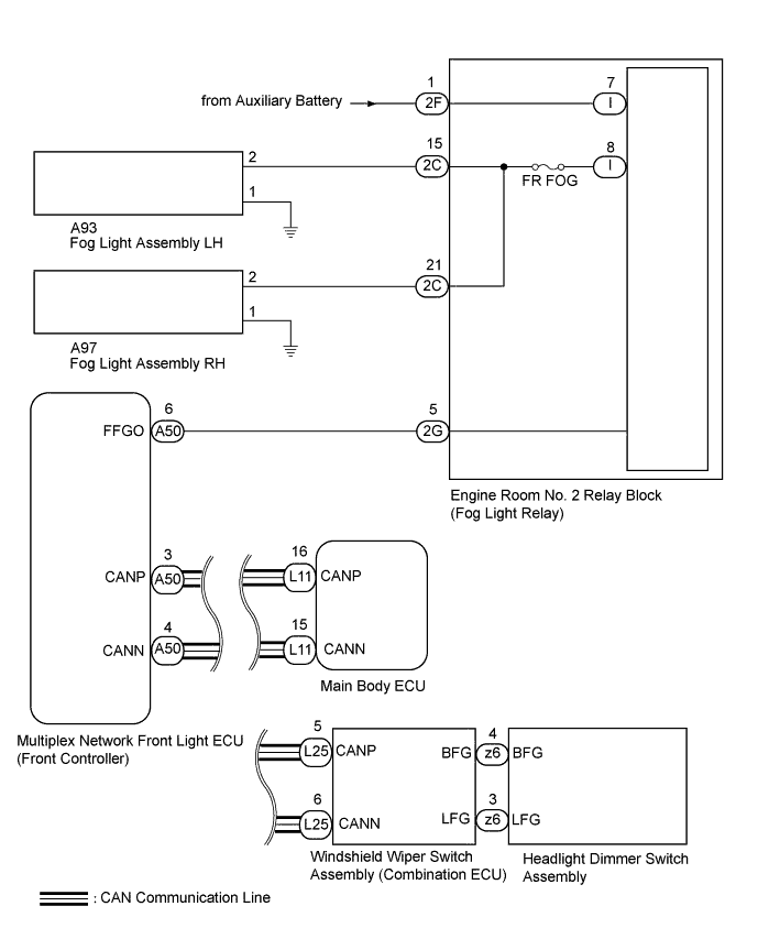
WIRING DIAGRAM
INSPECTION PROCEDURE
Note
-
First perform the communication function inspections in HOW TO PROCEED WITH TROUBLESHOOTING to confirm that there are no CAN communication malfunctions before troubleshooting this symptom.
-
Inspect the fuses for circuits related to this system before performing the following inspection procedure.
PROCEDURE
-
PERFORM ACTIVE TEST USING GTS (FRONT FOG LIGHT)
-
Using the GTS, perform the Active Test Click here.
Body No. 5 Tester Display Test Part Control Range Front Fog Light Relay Front fog light illumination operation OFF - ON OK Front fog light condition is switched by Active Test Result Result Proceed to NG A OK B
B 
READ VALUE USING GTS (HEADLIGHT DIMMER SWITCH) Click here
A 
-
-
CHECK MULTIPLEX NETWORK FRONT LIGHT ECU (FFGO VOLTAGE)
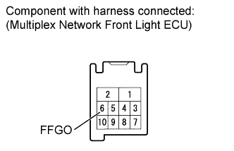
-
Remove the multiplex network front light ECU with its connector still connected.
-
Measure the voltage according to the value(s) in the table below.
Standard Voltage Tester Connection Switch Condition Specified Condition 6 (FFGO) - Body ground Headlight dimmer switch (Fr FOG) OFF 11 to 14 V 6 (FFGO) - Body ground Headlight dimmer switch (Fr FOG) ON Below 1 V
NG
CHECK HARNESS AND CONNECTOR (MULTIPLEX NETWORK FRONT LIGHT ECU - ENGINE ROOM NO. 2 RELAY BLOCK) Click here
OK
-
-
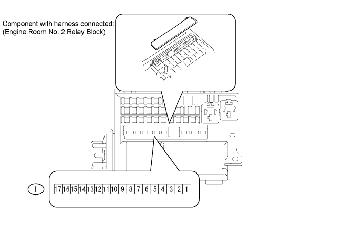
CHECK ENGINE ROOM NO. 2 RELAY BLOCK
-
Measure the voltage according to the value(s) in the table below.
Standard Voltage Tester Connection Switch Condition Specified Condition I-8 - Body ground Headlight dimmer switch (Fr FOG) ON 11 to 14 V
NG 
REPLACE ENGINE ROOM NO. 2 RELAY BLOCK
OK
-
-
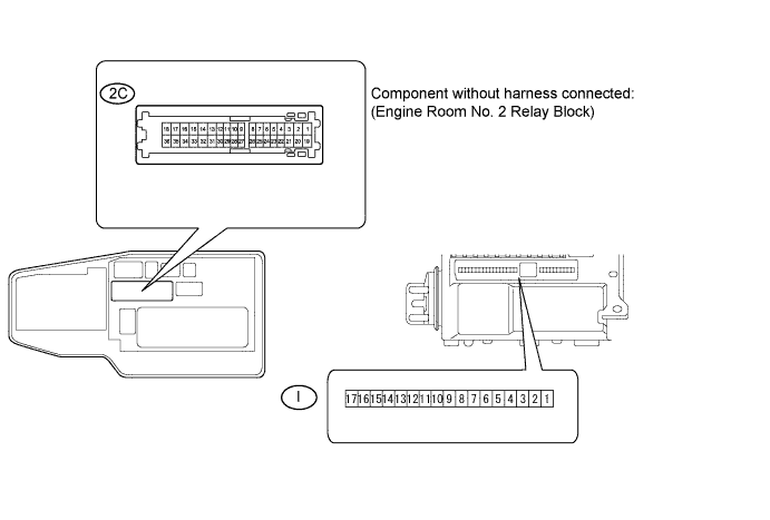
INSPECT ENGINE ROOM NO. 2 RELAY BLOCK
-
Disconnect the 2C engine room No. 2 relay block connector.
-
Measure the resistance according to the value(s) in the table below.
Standard Resistance Tester Connection Condition Specified Condition 2C-15 - I-8 Always Below 1 Ω 2C-21 - I-8 Always Below 1 Ω
NG
REPLACE ENGINE ROOM NO. 2 RELAY BLOCK
OK
-
-
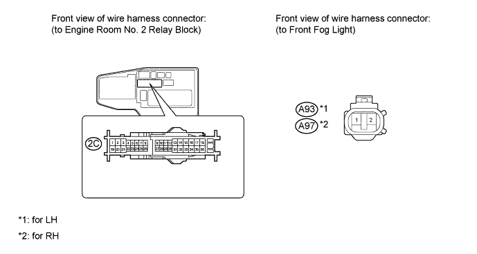
CHECK HARNESS AND CONNECTOR (ENGINE ROOM NO. 2 RELAY BLOCK - FOG LIGHT)
-
Disconnect the 2C engine room No. 2 relay block connector.
-
Disconnect the A93*1 or A97*2 fog light connector.
-
*1: for LH
-
*2: for RH
-
-
Measure the resistance according to the value(s) in the table below.
Standard Resistance for LH Tester Connection Condition Specified Condition 2C-15 - A93-2 Always Below 1 Ω A93-1 - Body ground Always Below 1 Ω 2C-15 - Body ground Always 10 kΩ or higher for RH Tester Connection Condition Specified Condition 2C-21 - A97-2 Always Below 1 Ω A97-1 - Body ground Always Below 1 Ω 2C-21 - Body ground Always 10 kΩ or higher Result Result Proceed to OK (for Sport Package) A OK (except Sport Package) B NG C
B
REPLACE FOG LIGHT ASSEMBLY Click here
C
REPAIR OR REPLACE HARNESS OR CONNECTOR
A 
REPLACE FOG LIGHT ASSEMBLY Click here
-
-
READ VALUE USING GTS (HEADLIGHT DIMMER SWITCH)
-
Using the GTS, read the Data List Click here.
Combination Switch Tester Display Measurement Item/Display Normal Condition Diagnostic Note Front Fog Light Switch Headlight dimmer switch signal (Fr fog position)/ON or OFF ON: Front fog light switch ON
OFF: Front fog light switch OFF
- OK Condition sign can be displayed
NG
REPLACE HEADLIGHT DIMMER SWITCH Click here
OK
-
-
CHECK WINDSHIELD WIPER SWITCH (OPERATION)
-
Temporarily replace the windshield wiper switch with a new or normally functioning one Click here.
-
Check the windshield wiper switch operation.
OK Windshield wiper switch operation is normal
NG
CHECK MULTIPLEX NETWORK FRONT LIGHT ECU (OPERATION) Click here
OK
END (WINDSHIELD WIPER SWITCH WAS DEFECTIVE)
-
-
CHECK MULTIPLEX NETWORK FRONT LIGHT ECU (OPERATION)
-
Temporarily replace the multiplex network front light ECU with a new or normally functioning one.
-
Check the front fog light operation.
OK Front fog light operation is normal
NG
REPLACE MAIN BODY ECU (DRIVER SIDE JUNCTION BLOCK ASSEMBLY)
OK
END (MULTIPLEX NETWORK FRONT LIGHT ECU WAS DEFECTIVE)
-
-
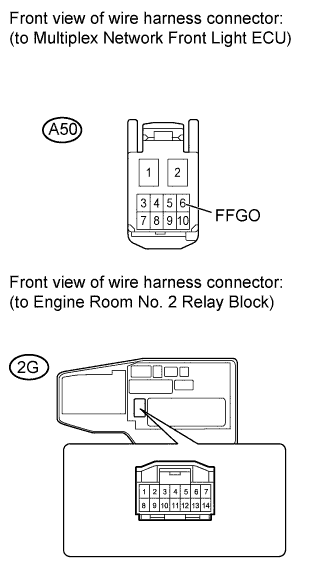
CHECK HARNESS AND CONNECTOR (MULTIPLEX NETWORK FRONT LIGHT ECU - ENGINE ROOM NO. 2 RELAY BLOCK)
-
Disconnect the A50 multiplex network front light ECU connector.
-
Disconnect the 2G engine room No. 2 relay block connector.
-
Measure the resistance according to the value(s) in the table below.
Standard Resistance Tester Connection Condition Specified Condition A50-6 (FFGO) - 2G-5 Always Below 1 Ω A50-6 (FFGO) - Body ground Always 10 kΩ or higher
NG
REPAIR OR REPLACE HARNESS OR CONNECTOR
OK
-
-
CHECK ENGINE ROOM NO. 2 RELAY BLOCK
-
Measure the voltage according to the value(s) in the table below.
Standard Voltage Tester Connection Condition Specified Condition I-7 - Body ground Always 11 to 14 V
NG
INSPECT ENGINE ROOM NO. 2 RELAY BLOCK Click here
OK
REPLACE ENGINE ROOM NO. 2 RELAY BLOCK
-
-
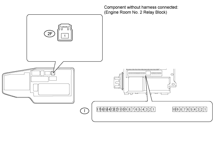
INSPECT ENGINE ROOM NO. 2 RELAY BLOCK
-
Disconnect the 2F engine room No. 2 relay block connector.
-
Measure the resistance according to the value(s) in the table below.
Standard Resistance Tester Connection Condition Specified Condition 2F-1 - I-7 Always Below 1 Ω
NG
REPLACE ENGINE ROOM NO. 2 RELAY BLOCK
OK
REPAIR OR REPLACE HARNESS OR CONNECTOR (BATTERY - ENGINE ROOM NO. 2 RELAY BLOCK)
-