LIGHTING SYSTEM Automatic Light Control Function does not Operate
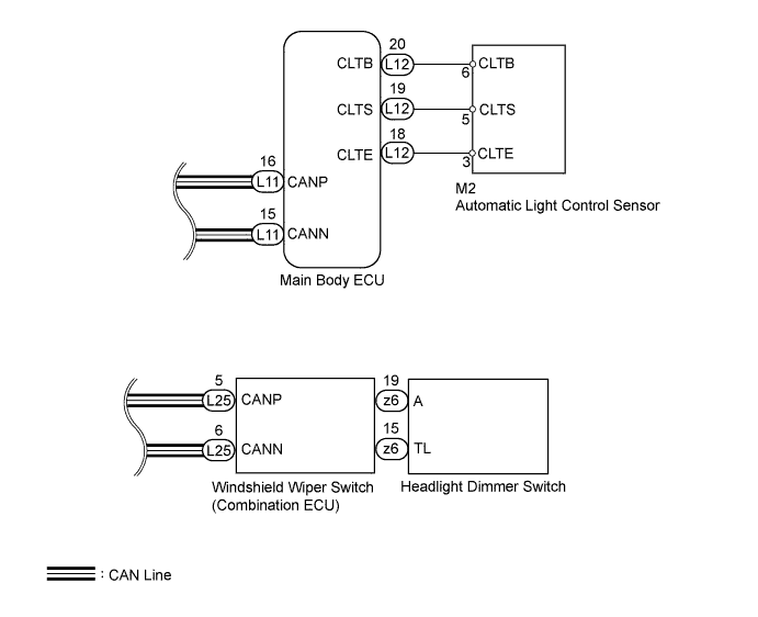
WIRING DIAGRAM
INSPECTION PROCEDURE
Note
First perform the communication function inspections in HOW TO PROCEED WITH TROUBLESHOOTING to confirm that there are no CAN communication malfunctions before troubleshooting this symptom.
PROCEDURE
-
READ VALUE USING GTS (AUTOMATIC LIGHT CONTROL SENSOR)
-
Using the GTS, read the Data List.
Main Body Tester Display Measurement Item / Range Normal Condition Diagnostic Note Illumination Rate Info Condition of automatic light control sensor/0 to 2162.65 ms Condition value will be displayed - OK Condition sign can be displayed.
NG 
CHECK HARNESS AND CONNECTOR (MAIN BODY ECU - AUTOMATIC LIGHT CONTROL SENSOR AND BODY GROUND) Click here
OK 
-
-
READ VALUE USING GTS (HEADLIGHT DIMMER SWITCH)
-
Using the GTS, read the Data List.
Combination Switch Tester Display Measurement Item / Range Normal Condition Diagnostic Note Light Auto Switch Headlight dimmer switch signal (AUTO position) / ON or OFF ON: Headlight dimmer switch AUTO position
OFF: Headlight dimmer switch OFF
- OK Condition sign can be displayed.
NG 
REPLACE MAIN BODY ECU
OK
-
-
CHECK WINDSHIELD WIPER SWITCH (OPERATION)
-
Temporarily replace the windshield wiper switch with a new or normally functioning one Click here.
-
Check the windshield wiper switch operation.
OK Windshield wiper switch operation is normal.
NG
REPLACE MAIN BODY ECU
OK 
END (REPLACE WINDSHIELD WIPER SWITCH) Click here
-
-
CHECK HARNESS AND CONNECTOR (MAIN BODY ECU - AUTOMATIC LIGHT CONTROL SENSOR AND BODY GROUND)
-
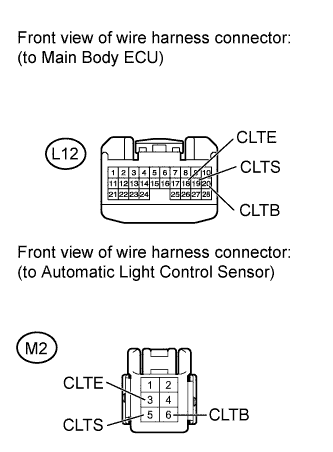
Disconnect the L12 ECU connector.
-
Disconnect the M2 sensor connector.
-
Measure the resistance according to the value(s) in the table below.
Standard resistance Tester Connection Condition Specified Condition L12-20 (CLTB) - M2-6 (CLTB) Always Below 1 Ω L12-19 (CLTS) - M2-5 (CLTS) Always Below 1 Ω L12-18 (CLTE) - M2-3 (CLTE) Always Below 1 Ω L12-20 (CLTB) - Body ground Always 10 kΩ or higher L12-19 (CLTS) - Body ground Always 10 kΩ or higher L12-18 (CLTE) - Body ground Always 10 kΩ or higher
NG
REPAIR OR REPLACE HARNESS OR CONNECTOR
OK
-
-
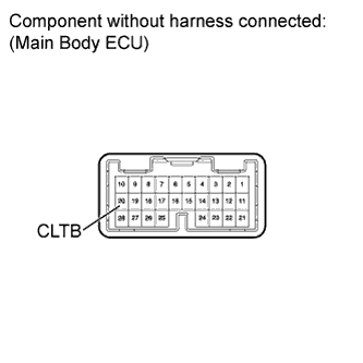
CHECK MAIN BODY ECU (CLTB VOLTAGE)
-
Disconnect the L12 ECU connector.
-
Measure the voltage according to the value(s) in the table below.
Standard voltage Tester Connection Switch Condition Specified Condition 20 (CLTB) - Body ground Power switch ON (IG) 11 to 14 V
NG
REPLACE MAIN BODY ECU
OK
REPLACE AUTOMATIC LIGHT CONTROL SENSOR Click here
-