LIGHTING SYSTEM Driver Side Instrument Panel Illumination does not Turn On
WIRING DIAGRAM
Refer to the wiring diagram for "Instrument Panel Illumination does not Turn On" Click here.
INSPECTION PROCEDURE
Note
Inspect the fuses for circuits related to this system before performing the following inspection procedure.
PROCEDURE
-
CHECK CONNECTOR CONNECTION CONDITION (NO. 2 INSTRUMENT PANEL GARNISH [DRIVER SIDE INSTRUMENT PANEL ILLUMINATION])
-
Check the connection of connector of the No. 2 instrument panel garnish (driver side instrument panel illumination).
OK The connector is connected securely and there are no contact problems.
NG 
CONNECT SECURELY
OK 
-
-
CHECK CONNECTOR CONNECTION CONDITION (NO. 1 INSTRUMENT PANEL GARNISH [PASSENGER SIDE INSTRUMENT PANEL ILLUMINATION])
-
Check the connection of connector of the No. 1 instrument panel garnish (passenger side instrument panel illumination).
OK The connector is connected securely and there are no contact problems.
NG
CONNECT SECURELY
OK
-
-
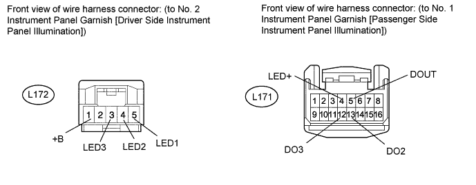
CHECK HARNESS AND CONNECTOR (NO. 1 INSTRUMENT PANEL GARNISH [PASSENGER SIDE INSTRUMENT PANEL ILLUMINATION] - NO. 2 INSTRUMENT PANEL GARNISH [DRIVER SIDE INSTRUMENT PANEL ILLUMINATION]
-
Disconnect the L171 No. 1 instrument panel garnish (passenger side instrument panel illumination) connector.
-
Disconnect the L172 No. 2 instrument panel garnish (driver side instrument panel illumination) connector.
-
Measure the resistance according to the value(s) in the table below.
Standard Resistance Tester Connection Condition Specified Condition L172-1 (+B) - L171-4 (LED+) Always Below 1 Ω L172-1 (+B) - Body ground Always 10 kΩ or higher L172-5 (LED1) - L171-5 (DOUT) Always Below 1 Ω L172-5 (LED1) - Body ground Always 10 kΩ or higher L172-4 (LED2) - L171-13 (DO2) Always Below 1 Ω L172-4 (LED2) - Body ground Always 10 kΩ or higher L172-3 (LED3) - L171-12 (DO3) Always Below 1 Ω L172-3 (LED3) - Body ground Always 10 kΩ or higher
NG
REPAIR OR REPLACE HARNESS OR CONNECTOR
OK
-
-
CHECK NO. 2 INSTRUMENT PANEL GARNISH SUB-ASSEMBLY (DRIVER SIDE INSTRUMENT PANEL ILLUMINATION)
-
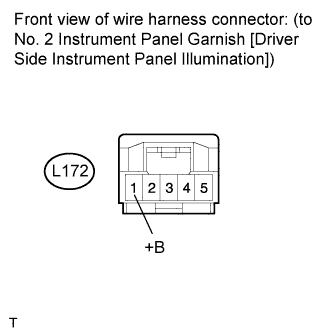
Disconnect the L172 No. 2 instrument panel garnish (driver side instrument panel illumination) connector.
-
Measure the voltage according to the value(s) in the table below.
Standard Voltage Tester Connection Condition Specified Condition L172-1 (+B) - Body ground Instrument panel illumination is off (when not in sleep mode [20 minutes within opening any door]) 7.5 to 8.5 V
NG
REPLACE NO. 1 INSTRUMENT PANEL GARNISH SUB-ASSEMBLY (PASSENGER SIDE INSTRUMENT PANEL ILLUMINATION) Click here
OK
-
-
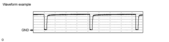
CHECK WAVEFORM
-
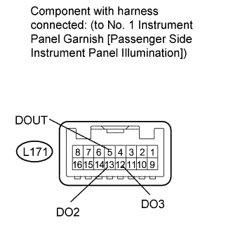
Connect an oscilloscope to the No. 1 instrument panel garnish (passenger side instrument panel illumination) connector.
-
Using an oscilloscope, check the signal waveform of the ECU.
Item Content Terminal No. (Symbol)
-
L171-5 (DOUT) - Body ground
-
L171-13 (DO2) - Body ground
-
L171-12 (DO3) - Body ground
Tool Setting 1 V/DIV., 2 ms/DIV. Condition Power switch on (IG), instrument panel illumination being dimmed after shift position moved from P OK The waveform is output as shown in the illustration. -
NG
REPLACE NO. 1 INSTRUMENT PANEL GARNISH SUB-ASSEMBLY (PASSENGER SIDE INSTRUMENT PANEL ILLUMINATION) Click here
OK 
REPLACE NO. 2 INSTRUMENT PANEL GARNISH SUB-ASSEMBLY (DRIVER SIDE INSTRUMENT PANEL ILLUMINATION) Click here
-