LIGHTING SYSTEM Inside Handle Light does not Illuminate
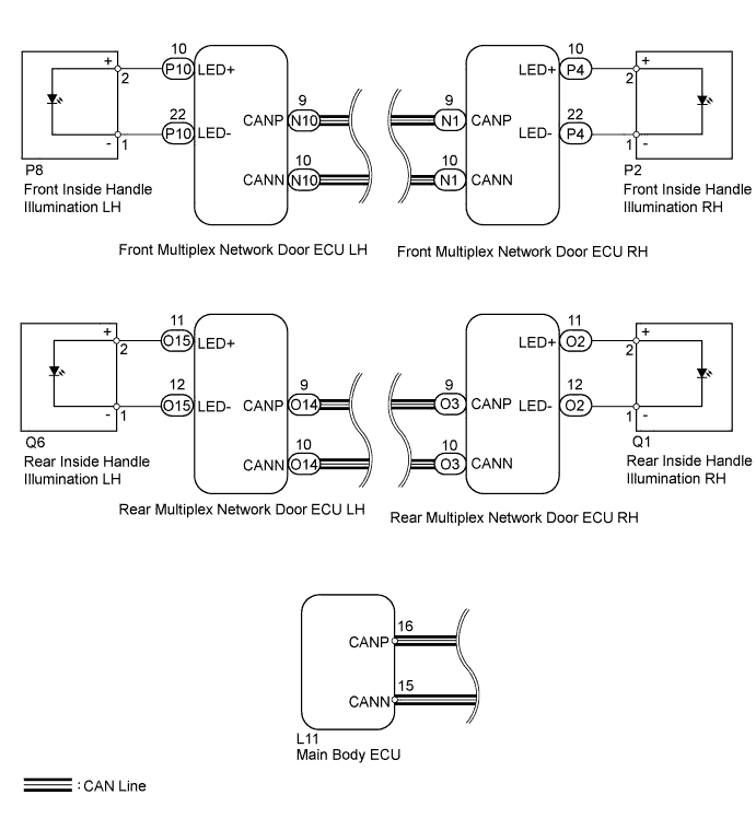
WIRING DIAGRAM
INSPECTION PROCEDURE
Note
First perform the communication function inspections in HOW TO PROCEED WITH TROUBLESHOOTING to confirm that there are no CAN communication malfunctions before troubleshooting this symptom.
PROCEDURE
-
CONFIRM LIGHT POSITION
-
Check the malfunctioning inside handle light.
Result Result Proceed to Front LH A Front RH B Rear LH C Rear RH D All E
B 
PERFORM ACTIVE TEST USING GTS (INSIDE HANDLE ILLUMINATION) Click here
C
PERFORM ACTIVE TEST USING GTS (INSIDE HANDLE ILLUMINATION) Click here
D
PERFORM ACTIVE TEST USING GTS (INSIDE HANDLE ILLUMINATION) Click here
E 
REPLACE MAIN BODY ECU
A 
-
-
PERFORM ACTIVE TEST USING GTS (INSIDE HANDLE ILLUMINATION)
-
Using the GTS, read the Data List.
Driver Door (for LHD) Tester Display Test Part Control Range Diagnostic Note Inside Handle Illumination Inside handle illumination operation OFF / ON - Passenger Door (for RHD) Tester Display Test Part Control Range Diagnostic Note Inside Handle Illumination Inside handle illumination operation OFF / ON - OK Inside handle illumination condition is switched by Active Test.
NG
INSPECT FRONT INSIDE HANDLE ILLUMINATION LH Click here
OK 
REPLACE MAIN BODY ECU
-
-
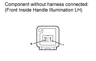
INSPECT FRONT INSIDE HANDLE ILLUMINATION LH
-
Remove the front inside handle light LH Click here.
-
Apply auxiliary battery voltage to the inside handle illumination and check the illumination condition.
OK Measurement Condition Specified Condition Auxiliary battery positive (+) → Terminal 2 (+)
Auxiliary battery negative (-) → Terminal 1 (-)
Inside handle light illumination on
NG
REPLACE FRONT INSIDE HANDLE ILLUMINATION LH Click here
OK
-
-
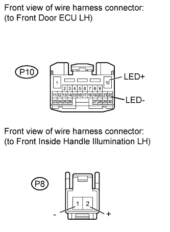
CHECK HARNESS AND CONNECTOR (FRONT DOOR ECU LH - FRONT INSIDE HANDLE ILLUMINATION LH)
-
Disconnect the P10 ECU connector.
-
Disconnect the P8 light connector.
-
Measure the resistance according to the value(s) in the table below.
Standard resistance Tester Connection Condition Specified Condition P8-1 (-) - P10-22 (LED-) Always Below 1 Ω P8-2 (+) - P10-10 (LED+) Always Below 1 Ω P8-1 (-) - Body ground Always 10 kΩ or higher P8-2 (+) - Body ground Always 10 kΩ or higher
NG
REPAIR OR REPLACE HARNESS OR CONNECTOR
OK
REPLACE FRONT MULTIPLEX NETWORK DOOR ECU LH Click here
-
-
PERFORM ACTIVE TEST USING GTS (INSIDE HANDLE ILLUMINATION)
-
Using the GTS, perform the Active Test.
Passenger Door (for LHD) Tester Display Test Part Control Range Diagnostic Note Inside Handle Illumination Inside handle illumination operation OFF / ON - Driver Door (for RHD) Tester Display Test Part Control Range Diagnostic Note Inside Handle Illumination Inside handle illumination operation OFF / ON - OK Inside handle illumination condition is switched by Active Test.
NG
INSPECT FRONT INSIDE HANDLE ILLUMINATION RH Click here
OK
REPLACE MAIN BODY ECU
-
-
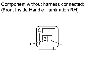
INSPECT FRONT INSIDE HANDLE ILLUMINATION RH
-
Remove the front inside handle light RH Click here.
-
Apply auxiliary battery voltage to the inside handle illumination and check the illumination condition.
OK Measurement Condition Specified Condition Auxiliary battery positive (+) → Terminal 2 (+)
Auxiliary battery negative (-) → Terminal 1 (-)
Inside handle light illumination on
NG
REPLACE FRONT INSIDE HANDLE ILLUMINATION RH Click here
OK
-
-
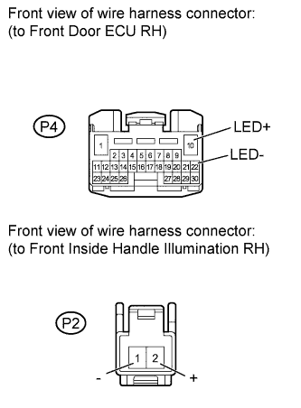
CHECK HARNESS AND CONNECTOR (FRONT DOOR ECU RH - FRONT INSIDE HANDLE ILLUMINATION RH)
-
Disconnect the P4 ECU connector.
-
Disconnect the P2 light connector.
-
Measure the resistance according to the value(s) in the table below.
Standard resistance Tester Connection Condition Specified Condition P2-1 (-) - P4-22 (LED-) Always Below 1 Ω P2-2 (+) - P4-10 (LED+) Always Below 1 Ω P2-2 (+) - Body ground Always 10 kΩ or higher P2-1 (-) - Body ground Always 10 kΩ or higher
NG
REPAIR OR REPLACE HARNESS OR CONNECTOR
OK
REPLACE FRONT MULTIPLEX NETWORK DOOR ECU RH Click here
-
-
PERFORM ACTIVE TEST USING GTS (INSIDE HANDLE ILLUMINATION)
-
Using the GTS, perform the Active Test.
Rear Left Door Tester Display Test Part Control Range Diagnostic Note Inside Handle Illumination Inside handle illumination operation OFF / ON - OK Inside handle illumination condition is switched by Active Test.
NG
INSPECT REAR INSIDE HANDLE ILLUMINATION LH Click here
OK
REPLACE MAIN BODY ECU
-
-
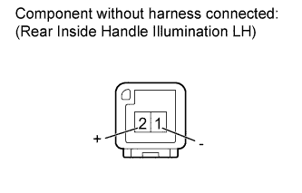
INSPECT REAR INSIDE HANDLE ILLUMINATION LH
-
Remove the rear inside handle light LH Click here.
-
Apply auxiliary battery voltage to the inside handle illumination and check the illumination condition.
OK Measurement Condition Specified Condition Auxiliary battery positive (+) → Terminal 2 (+)
Auxiliary battery negative (-) → Terminal 1 (-)
Inside handle light illumination on
NG
REPLACE REAR INSIDE HANDLE ILLUMINATION LH Click here
OK
-
-
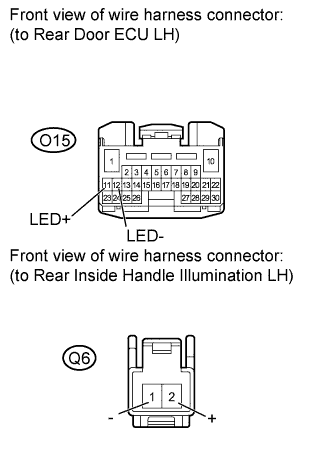
CHECK HARNESS AND CONNECTOR (REAR DOOR ECU LH - REAR INSIDE HANDLE ILLUMINATION LH)
-
Disconnect the O15 ECU connector.
-
Disconnect the Q6 light connector.
-
Measure the resistance according to the value(s) in the table below.
Standard resistance Tester Connection Condition Specified Condition Q6-1 (-) - O15-12 (LED-) Always Below 1 Ω Q6-2 (+) - O15-11 (LED+) Always Below 1 Ω Q6-1 (-) - Body ground Always 10 kΩ or higher Q6-2 (+) - Body ground Always 10 kΩ or higher Result Result Proceed to OK (for Standard Body) A OK (for Long Body) B NG C
B
REPLACE REAR MULTIPLEX NETWORK DOOR ECU LH Click here
C
REPAIR OR REPLACE HARNESS OR CONNECTOR
A
REPLACE REAR MULTIPLEX NETWORK DOOR ECU LH Click here
-
-
PERFORM ACTIVE TEST USING GTS (INSIDE HANDLE ILLUMINATION)
-
Using the GTS, perform the Active Test.
Rear Right Door Tester Display Test Part Control Range Diagnostic Note Inside Handle Illumination Inside handle illumination operation OFF / ON - OK Inside handle illumination condition is switched by Active Test.
NG
INSPECT REAR INSIDE HANDLE ILLUMINATION RH ASSEMBLY Click here
OK
REPLACE MAIN BODY ECU
-
-
INSPECT REAR INSIDE HANDLE ILLUMINATION RH ASSEMBLY

-
Remove the rear inside handle light RH Click here.
-
Apply auxiliary battery voltage to the inside handle illumination and check the illumination condition.
OK Measurement Condition Specified Condition Auxiliary battery positive (+) → Terminal 2 (+)
Auxiliary battery negative (-) → Terminal 1 (-)
Inside handle light illumination on
NG
REPLACE REAR INSIDE HANDLE ILLUMINATION RH Click here
OK
-
-
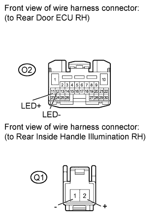
CHECK HARNESS AND CONNECTOR (REAR DOOR ECU RH - REAR INSIDE HANDLE ILLUMINATION RH)
-
Disconnect the O2 ECU connector.
-
Disconnect the Q1 light connector.
-
Measure the resistance according to the value(s) in the table below.
Standard resistance Tester Connection Condition Specified Condition Q1-1 (-) - O2-12 (LED-) Always Below 1 Ω Q1-2 (+) - O2-11 (LED+) Always Below 1 Ω Q1-1 (-) - Body ground Always 10 kΩ or higher Q1-2 (+) - Body ground Always 10 kΩ or higher
NG
REPAIR OR REPLACE HARNESS OR CONNECTOR
OK
REPLACE REAR MULTIPLEX NETWORK DOOR ECU RH Click here
-