LIGHTING SYSTEM Stop Light does not Illuminate
WIRING DIAGRAM
INSPECTION PROCEDURE
Note
-
Check if DTC B2402 is output. If output, refer to the following procedures Click here.
-
Inspect the fuses for circuits related to this system before performing the following inspection procedure.
Tech Tips
With the power switch off, if the rear junction block ECU is in sleep mode or is malfunctioning, the fail-safe line in the rear junction block ECU operates light illuminations.
PROCEDURE
-
CONFIRM LIGHT POSITION
-
Check the malfunctioning stop light.
Result Result Proceed to Stop light (built into rear combination light) A Stop light (built into rear light) B Center stop light C All lights do not illuminate D Stop lights blink (w/ Emergency Stop Light) E
B 
CHECK REAR JUNCTION BLOCK ECU (STP3 VOLTAGE) Click here
C
CHECK REAR JUNCTION BLOCK ECU (STP4 VOLTAGE) Click here
D
PERFORM ACTIVE TEST USING GTS (STOP LIGHT) Click here
E
CHECK DTC (BRAKE CONTROL SYSTEM) Click here
A 
-
-
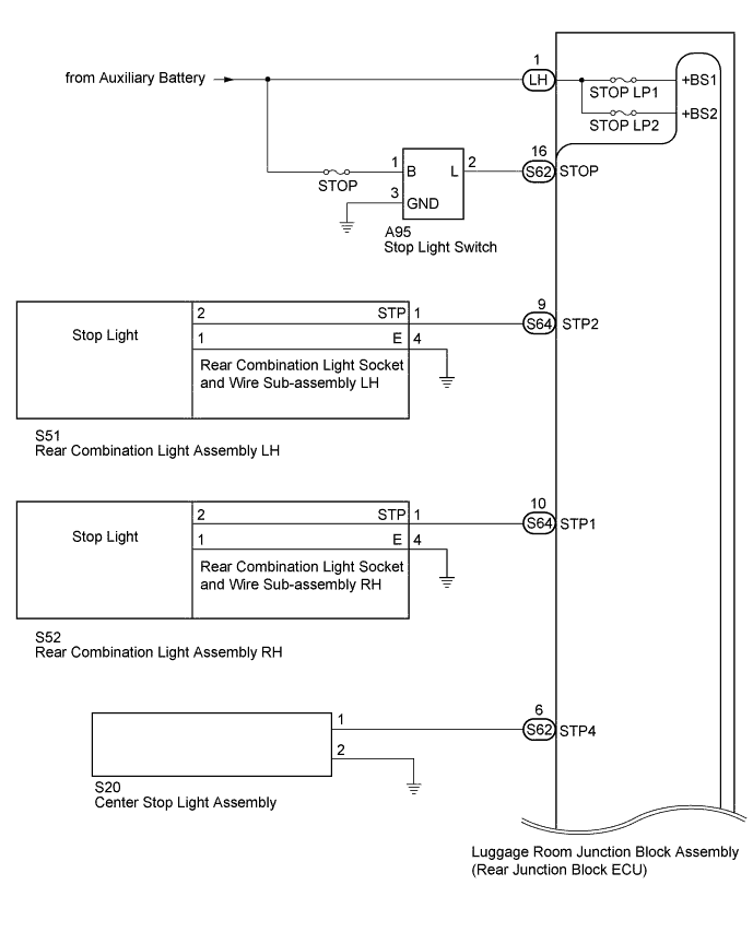
CHECK REAR JUNCTION BLOCK ECU (STP1, STP2 VOLTAGE)
-
Disconnect the S64 rear junction block ECU connector.
-
Measure the voltage according to the value(s) in the table below.
Standard Voltage Tester Connection Switch Condition Specified Condition 9 (STP2) - Body ground Brake pedal depressed 11 to 14 V 9 (STP2) - Body ground Brake pedal not depressed Below 1 V 10 (STP1) - Body ground Brake pedal depressed 11 to 14 V 10 (STP1) - Body ground Brake pedal not depressed Below 1 V
NG 
REPLACE LUGGAGE ROOM JUNCTION BLOCK (REAR JUNCTION BLOCK ECU)
OK
-
-
CHECK HARNESS AND CONNECTOR (REAR COMBINATION LIGHT - REAR JUNCTION BLOCK ECU AND BODY GROUND)
-
Disconnect the S64 rear junction block ECU connector.
-
Disconnect the S51*1 or S52*2 rear combination light connector.
-
*1: for LH
-
*2: for RH
-
-
Measure the resistance according to the value(s) in the table below.
Standard Resistance for LH Tester Connection Condition Specified Condition S64-9 (STP2) - S51-1 (STP) Always Below 1 Ω S51-4 (E) - Body ground Always Below 1 Ω S64-9 (STP2) - Body ground Always 10 kΩ or higher for RH Tester Connection Condition Specified Condition S64-10 (STP1) - S52-1 (STP) Always Below 1 Ω S52-4 (E) - Body ground Always Below 1 Ω S64-10 (STP1) - Body ground Always 10 kΩ or higher
NG
REPAIR OR REPLACE HARNESS OR CONNECTOR
OK
-
-
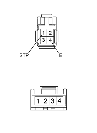
INSPECT REAR COMBINATION LIGHT SOCKET AND WIRE SUB-ASSEMBLY
-
Remove the rear combination light socket and wire Click here.
-
Measure the resistance according to the value(s) in the table below.
Standard Resistance Tester Connection Condition Specified Condition 1 (STP) - 2 Always Below 1 Ω 4 (E) - 1 Always Below 1 Ω
NG
REPLACE REAR COMBINATION LIGHT SOCKET AND WIRE SUB-ASSEMBLY Click here
OK 
REPLACE REAR COMBINATION LIGHT ASSEMBLY Click here
-
-
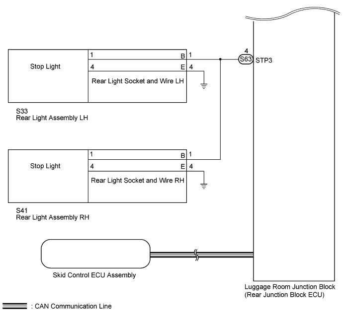
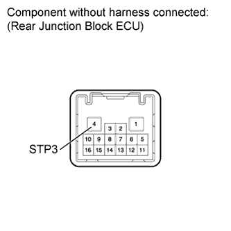
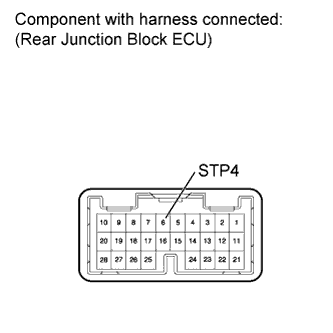
CHECK REAR JUNCTION BLOCK ECU (STP3 VOLTAGE)
-
Disconnect the S63 rear junction block ECU connector.
-
Measure the voltage according to the value(s) in the table below.
Standard Voltage Tester Connection Switch Condition Specified Condition 4 (STP3) - Body ground Brake pedal depressed 11 to 14 V 4 (STP3) - Body ground Brake pedal not depressed Below 1 V
NG
REPLACE LUGGAGE ROOM JUNCTION BLOCK (REAR JUNCTION BLOCK ECU)
OK
-
-
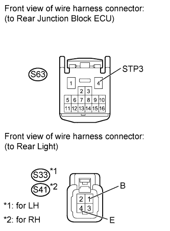
CHECK HARNESS AND CONNECTOR (REAR LIGHT - REAR JUNCTION BLOCK ECU AND BODY GROUND)
-
Disconnect the S63 rear junction block ECU connector.
-
Disconnect the S33*1 or S41*2 rear light connector.
-
*1: for LH
-
*2: for RH
-
-
Measure the resistance according to the value(s) in the table below.
Standard Resistance for LH Tester Connection Condition Specified Condition S63-4 (STP3) - S33-1 (B) Always Below 1 Ω S33-4 (E) - Body ground Always Below 1 Ω S63-4 (STP3) - Body ground Always 10 kΩ or higher for RH Tester Connection Condition Specified Condition S63-4 (STP3) - S41-1 (B) Always Below 1 Ω S41-4 (E) - Body ground Always Below 1 Ω S63-4 (STP3) - Body ground Always 10 kΩ or higher
NG
REPAIR OR REPLACE HARNESS OR CONNECTOR
OK
-
-
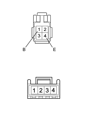
INSPECT REAR LIGHT SOCKET AND WIRE
-
Remove the rear light socket and wire Click here.
-
Measure the resistance according to the value(s) in the table below.
Standard Resistance Tester Connection Condition Specified Condition 1 (B) - 1 Always Below 1 Ω 4 (E) - 4 Always Below 1 Ω
NG
REPLACE REAR LIGHT SOCKET AND WIRE Click here
OK
REPLACE REAR LIGHT ASSEMBLY Click here
-
-
CHECK REAR JUNCTION BLOCK ECU (STP4 VOLTAGE)
-
Remove the S62 rear junction block ECU with its connector still connected.
-
Measure the voltage according to the value(s) in the table below.
Standard Voltage Tester Connection Switch Condition Specified Condition 6 (STP4) - Body ground Brake pedal depressed 11 to 14 V 6 (STP4) - Body ground Brake pedal not depressed Below 1 V
NG
REPLACE LUGGAGE ROOM JUNCTION BLOCK (REAR JUNCTION BLOCK ECU)
OK
-
-
CHECK HARNESS AND CONNECTOR (CENTER STOP LIGHT - REAR JUNCTION BLOCK ECU AND BODY GROUND)
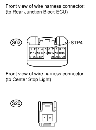
-
Disconnect the S62 rear junction block ECU connector.
-
Disconnect the S20 center stop light connector.
-
Measure the resistance according to the value(s) in the table below.
Standard Resistance Tester Connection Condition Specified Condition S62-6 (STP4) - S20-1 Always Below 1 Ω S20-2 - Body ground Always Below 1 Ω S62-6 (STP4) - Body ground Always 10 kΩ or higher
NG
REPAIR OR REPLACE HARNESS OR CONNECTOR
OK
REPLACE CENTER STOP LIGHT ASSEMBLY Click here
-
-
PERFORM ACTIVE TEST USING GTS (STOP LIGHT)
-
Using the GTS, perform the Active Test Click here.
Body No. 4 Tester Display Test Part Control Range Stop Light Stop light operation OFF-ON High Mount Stop Light High mount stop light operation OFF-ON OK Stop light condition is switched by Active Test.
NG
CHECK HARNESS AND CONNECTOR (REAR JUNCTION BLOCK ECU - BATTERY) Click here
OK
-
-
READ VALUE USING GTS (STOP LIGHT SWITCH)
-
Using the GTS, read the Data List Click here.
Body No. 4 Tester Display Measurement Item/Display Normal Condition Diagnostic Note Stop Light Switch Stop light switch/ON or OFF ON: Brake pedal depressed
OFF: Brake pedal released
- OK Condition sign can be displayed.
NG
CHECK HARNESS AND CONNECTOR (STOP LIGHT SWITCH - BATTERY AND BODY GROUND) Click here
OK
REPLACE LUGGAGE ROOM JUNCTION BLOCK (REAR JUNCTION BLOCK ECU)
-
-
CHECK HARNESS AND CONNECTOR (STOP LIGHT SWITCH - BATTERY AND BODY GROUND)
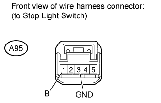
-
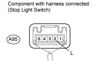
Disconnect the A95 stop light switch connector.
-
Measure the voltage according to the value(s) in the table below.
Standard Voltage Tester Connection Condition Specified Condition A95-1 (B) - Body ground Always 11 to 14 V -
Measure the resistance according to the value(s) in the table below.
Standard Resistance Tester Connection Condition Specified Condition A95-3 (GND) - Body ground Always Below 1 Ω
NG
REPAIR OR REPLACE HARNESS OR CONNECTOR
OK
-
-
CHECK HARNESS AND CONNECTOR (STOP LIGHT SWITCH - REAR JUNCTION BLOCK ECU)
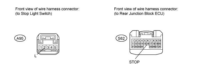
-
Disconnect the S62 rear junction block ECU connector.
-
Disconnect the A95 stop light switch connector.
-
Measure the resistance according to the value(s) in the table below.
Standard Resistance Tester Connection Condition Specified Condition A95-2 (L) - S62-16 (STOP) Always Below 1 Ω A95-2 (L) - Body ground Always 10 kΩ or higher
NG
REPAIR OR REPLACE HARNESS OR CONNECTOR
OK
-
-
CHECK STOP LIGHT SWITCH
-
Disconnect the S62 rear junction block ECU connector.
-
Measure the voltage according to the value(s) in the table below.
Standard Voltage Tester Connection Condition Specified Condition A95-2 (L) - Body ground Brake pedal depressed 11 to 14 V A95-2 (L) - Body ground Brake pedal released Below 1 V
NG
REPLACE STOP LIGHT SWITCH ASSEMBLY Click here
OK
REPLACE LUGGAGE ROOM JUNCTION BLOCK (REAR JUNCTION BLOCK ECU)
-
-
CHECK HARNESS AND CONNECTOR (REAR JUNCTION BLOCK ECU - BATTERY)
-
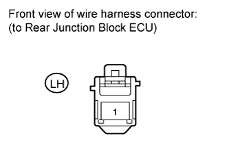
Disconnect the LH rear junction block ECU connector.
-
Measure the voltage according to the value(s) in the table below.
Standard Voltage Tester Connection Condition Specified Condition LH-1 - Body ground Always 11 to 14 V
NG
REPAIR OR REPLACE HARNESS OR CONNECTOR
OK
REPLACE LUGGAGE ROOM JUNCTION BLOCK (REAR JUNCTION BLOCK ECU)
-
-
CHECK DTC (BRAKE CONTROL SYSTEM)
-
Clear the DTC Click here.
-
Check for DTC Click here.
OK DTCs output does not occur
NG
GO TO ELECTRONICALLY CONTROLLED BRAKE SYSTEM Click here
OK
-
-
CHECK STOP LIGHT
-
With the skid control ECU connector disconnected, check the illumination of the stop lights when depressing the brake pedal.
OK Stop lights operate normally when the brake pedal is depressed. Result Result Proceed to OK (for LHD) A OK (for RHD) B NG C
B
REPLACE SKID CONTROL ECU ASSEMBLY Click here
C
REPLACE LUGGAGE ROOM JUNCTION BLOCK (REAR JUNCTION BLOCK ECU)
A
REPLACE SKID CONTROL ECU ASSEMBLY Click here
-