LIGHTING SYSTEM, Diagnostic DTC:B2442

| DTC Code | DTC Name |
|---|---|
| B2442 | Lost Communication with Camera Module |
DESCRIPTION
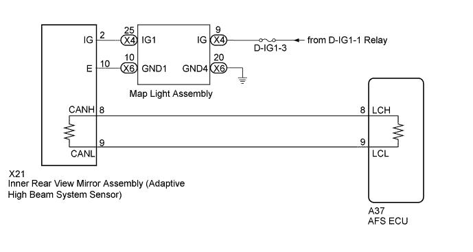
This DTC is output when there is a malfunction in the CAN communication between the AFS ECU and the inner rear view mirror assembly (adaptive high beam system sensor).
| DTC Code | DTC Detection Condition | Trouble Area |
|---|---|---|
| B2442 | Inner rear view mirror assembly (adaptive high beam system sensor) communication error |
|
WIRING DIAGRAM
INSPECTION PROCEDURE
Note
-
After replacing the inner rear view mirror assembly (adaptive high beam system sensor), it is necessary to initialize the inner rear view mirror assembly (adaptive high beam system sensor) beam axis Click here.
-
Before measuring the resistance of the CAN bus, turn the power switch off and leave the vehicle for 1 minute or more without operating the key, switches or opening or closing the doors. After that, disconnect the cable from the negative (-) auxiliary battery terminal and leave the vehicle for 1 minute or more before measuring the resistance.
-
After turning the power switch off, waiting time may be required before disconnecting the cable from the auxiliary battery terminal. Therefore, make sure to read the disconnecting the cable from the auxiliary battery terminal notice before proceeding with work Click here.
-
When disconnecting the cable, some systems need to be initialized after the cable is reconnected Click here.
-
Inspect the fuses for circuits related to this system before performing the following inspection procedure.
PROCEDURE
-
CLEAR DTC
-
Clear the DTC Click here.
NEXT 
-
-
CHECK FOR DTC
-
Turn the power switch on (IG).
-
Check for DTC Click here.
OK DTC B2442 output does not occur
NG 
CHECK HARNESS AND CONNECTOR (INNER REAR VIEW MIRROR [ADAPTIVE HIGH BEAM SYSTEM SENSOR] - BATTERY) Click here
OK 
USE SIMULATION METHOD TO CHECK Click here
-
-
CHECK HARNESS AND CONNECTOR (INNER REAR VIEW MIRROR [ADAPTIVE HIGH BEAM SYSTEM SENSOR] - BATTERY)
-
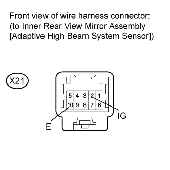
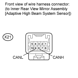
Disconnect the X21 inner rear view mirror (adaptive high beam system sensor) connector.
-
Measure the voltage according to the value(s) in the table below.
Standard Voltage Tester Connection Switch Condition Specified Condition X21-2 (IG) - X21-10 (E) Power switch on (IG) 11 to 14 V
NG
CHECK HARNESS AND CONNECTOR (MAP LIGHT - BATTERY AND BODY GROUND) Click here
OK
-
-
CHECK CAN BUS WIRE (CHECK LOCAL BUS FOR DISCONNECTION, CHECK LOCAL BUS FOR SHORT CIRCUIT)
-
Disconnect the cable from negative (-) auxiliary battery terminal.
-
Measure the resistance according to the value(s) in the table below.
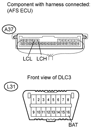
Standard Resistance Tester Connection Condition Specified Condition Resistance: Malfunction A37-8 (LCH) - A37-9 (LCL) Cable disconnected from negative (-) auxiliary battery terminal 54 to 69 Ω Below 53 Ω: Short in line A37-8 (LCH) - A37-9 (LCL) Cable disconnected from negative (-) auxiliary battery terminal 54 to 69 Ω Higher than 70 Ω: Open in CAN main bus line A37-8 (LCH) - L31-16 (BAT) Cable disconnected from negative (-) auxiliary battery terminal 6 kΩ or higher Below 6 kΩ: +B short A37-9 (LCL) - L31-16 (BAT) Cable disconnected from negative (-) auxiliary battery terminal 6 kΩ or higher Below 6 kΩ: +B short A37-8 (LCH) - Body ground Cable disconnected from negative (-) auxiliary battery terminal 200 Ω or higher Below 200 Ω: Ground short A37-9 (LCL) - Body ground Cable disconnected from negative (-) auxiliary battery terminal 200 Ω or higher Below 200 Ω: Ground short Result Result Proceed to OK A NG
-
Open in local bus
B NG
-
Short in line
-
+B short
-
GND short
C -
B
CHECK FOR OPEN IN CAN BUS WIRE (AFS ECU - INNER REAR VIEW MIRROR [ADAPTIVE HIGH BEAM SYSTEM SENSOR]) Click here
C
CHECK FOR SHORT IN CAN BUS WIRE (INNER REAR VIEW MIRROR [ADAPTIVE HIGH BEAM SYSTEM SENSOR] - AFS ECU) Click here
A
-
-
CHECK INNER REAR VIEW MIRROR ASSEMBLY (ADAPTIVE HIGH BEAM SYSTEM SENSOR)
-
Temporarily replace the inner rear view mirror (adaptive high beam system sensor) with a new or normally functioning one Click here.
-
Perform beam axis initialization for the inner rear view mirror assembly (adaptive high beam system sensor) Click here.
-
Turn the power switch on (IG).
-
Check for DTC Click here.
OK DTC B2442 output does not occur
NG 
REPLACE AFS ECU Click here
OK
END (INNER REAR VIEW MIRROR [ADAPTIVE HIGH BEAM SYSTEM SENSOR] WAS DEFECTIVE)
-
-
CHECK FOR OPEN IN CAN BUS WIRE (AFS ECU - INNER REAR VIEW MIRROR [ADAPTIVE HIGH BEAM SYSTEM SENSOR])
-
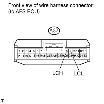
Disconnect the A37 AFS ECU connector.
-
Measure the resistance according to the value(s) in the table below.
Standard Resistance Tester Connection Condition Specified Condition A37-8 (LCH) - A37-9 (LCL) Cable disconnected from negative (-) auxiliary battery terminal 108 to 132 Ω
NG
CHECK FOR OPEN IN CAN BUS WIRE (INNER REAR VIEW MIRROR [ADAPTIVE HIGH BEAM SYSTEM SENSOR] - AFS ECU) Click here
OK
REPLACE AFS ECU Click here
-
-
CHECK FOR OPEN IN CAN BUS WIRE (INNER REAR VIEW MIRROR [ADAPTIVE HIGH BEAM SYSTEM SENSOR] - AFS ECU)
-
Disconnect the X21 inner rear view mirror (adaptive high beam system sensor) connector.
-
Measure the resistance according to the value(s) in the table below.
Standard Resistance Tester Connection Condition Specified Condition X21-8 (CANH) - X21-9 (CANL) Cable disconnected from negative (-) auxiliary battery terminal 108 to 132 Ω
NG
REPAIR OR REPLACE CAN MAIN WIRE OR CONNECTOR (INNER REAR VIEW MIRROR [ADAPTIVE HIGH BEAM SYSTEM SENSOR] - AFS ECU)
OK
REPLACE INNER REAR VIEW MIRROR ASSEMBLY (ADAPTIVE HIGH BEAM SYSTEM SENSOR) Click here
-
-
CHECK FOR SHORT IN CAN BUS WIRE (INNER REAR VIEW MIRROR [ADAPTIVE HIGH BEAM SYSTEM SENSOR] - AFS ECU)
-
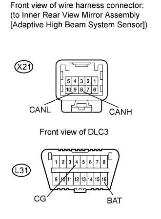
Disconnect the X21 inner rear view mirror (adaptive high beam system sensor) connector.
-
Measure the resistance according to the value(s) in the table below.
Standard Resistance Tester Connection Condition Specified Condition X21-8 (CANH) - X21-9 (CANL) Cable disconnected from negative (-) auxiliary battery terminal 108 to 132 Ω X21-8 (CANH) - L31-16 (BAT) Cable disconnected from negative (-) auxiliary battery terminal 6 kΩ or higher X21-9 (CANL) - L31-16 (BAT) Cable disconnected from negative (-) auxiliary battery terminal 6 kΩ or higher X21-8 (CANH) - L31-4 (CG) Cable disconnected from negative (-) auxiliary battery terminal 200 Ω or higher X21-9 (CANL) - L31-4 (CG) Cable disconnected from negative (-) auxiliary battery terminal 200 Ω or higher
NG
CHECK FOR SHORT IN CAN BUS WIRE (AFS ECU - INNER REAR VIEW MIRROR [ADAPTIVE HIGH BEAM SYSTEM SENSOR]) Click here
OK
REPLACE INNER REAR VIEW MIRROR ASSEMBLY (ADAPTIVE HIGH BEAM SYSTEM SENSOR) Click here
-
-
CHECK FOR SHORT IN CAN BUS WIRE (AFS ECU - INNER REAR VIEW MIRROR [ADAPTIVE HIGH BEAM SYSTEM SENSOR])
-
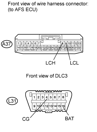
Disconnect the A37 AFS ECU connector.
-
Measure the resistance according to the value(s) in the table below.
Standard Resistance Tester Connection Condition Specified Condition A37-8 (LCH) - A37-9 (LCL) Cable disconnected from negative (-) auxiliary battery terminal 108 to 132 Ω A37-8 (LCH) - L31-16 (BAT) Cable disconnected from negative (-) auxiliary battery terminal 6 kΩ or higher A37-9 (LCL) - L31-16 (BAT) Cable disconnected from negative (-) auxiliary battery terminal 6 kΩ or higher A37-8 (LCH) - L31-4 (CG) Cable disconnected from negative (-) auxiliary battery terminal 200 Ω or higher A37-9 (LCL) - L31-4 (CG) Cable disconnected from negative (-) auxiliary battery terminal 200 Ω or higher
NG
REPAIR OR REPLACE CAN MAIN WIRE OR CONNECTOR (AFS ECU - INNER REAR VIEW MIRROR [ADAPTIVE HIGH BEAM SYSTEM SENSOR])
OK
REPLACE AFS ECU Click here
-
-
CHECK HARNESS AND CONNECTOR (MAP LIGHT - BATTERY AND BODY GROUND)
-
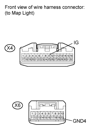
Disconnect the X4 and X6 map light connectors.
-
Measure the voltage according to the value(s) in the table below.
Standard Voltage Tester Connection Switch Condition Specified Condition X4-9 (IG) - Body ground Power switch on (IG) 11 to 14 V -
Measure the resistance according to the value(s) in the table below.
Standard Resistance Tester Connection Condition Specified Condition X6-20 (GND4) - Body ground Always Below 1 Ω
NG
REPAIR OR REPLACE HARNESS OR CONNECTOR
OK
-
-
CHECK HARNESS AND CONNECTOR (MAP LIGHT - INNER REAR VIEW MIRROR [ADAPTIVE HIGH BEAM SYSTEM SENSOR])
-
Disconnect the X4 and X6 map light connectors.
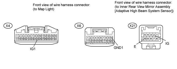
-
Disconnect the X21 inner rear view mirror (adaptive high beam system sensor) connector.
-
Measure the resistance according to the value(s) in the table below.
Standard Resistance Tester Connection Condition Specified Condition X4-25 (IG1) - X21-2 (IG) Always Below 1 Ω X6-10 (GND1) - X21-10 (E) Always Below 1 Ω X4-25 (IG1) - Body ground Always 10 kΩ or higher X6-10 (GND1) - Body ground Always 10 kΩ or higher
NG
REPAIR OR REPLACE HARNESS OR CONNECTOR
OK
REPLACE MAP LIGHT ASSEMBLY Click here
-