LIGHTING SYSTEM, Diagnostic DTC:B2430, B2431

| DTC Code | DTC Name |
|---|---|
| B2430 | LED Headlight LH Circuit Malfunction |
| B2431 | LED Headlight RH Circuit Malfunction |
DESCRIPTION
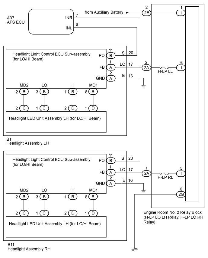
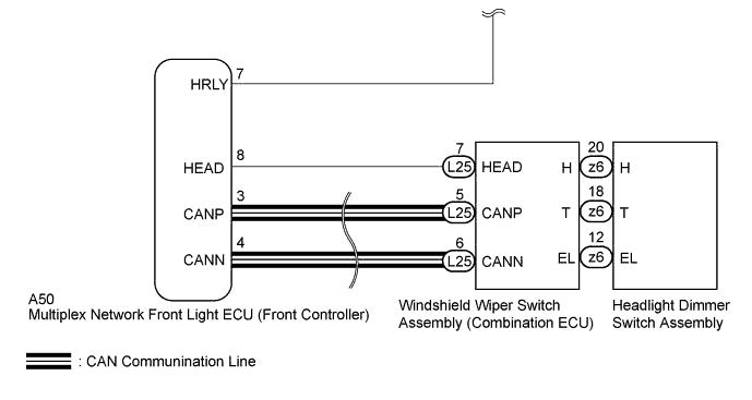
This DTC is output when the low beam headlights and high beam headlights do not illuminate, or a malfunction is detected in the communication between the headlight assembly and the AFS ECU. The multiplex network front light ECU (front controller) illuminates and turns off the low beam headlight via the engine room No. 2 relay block (H-LP LO LH, H-LP LO RH). The multiplex network front light ECU (front controller) detects the state of the headlight dimmer switch from the windshield wiper switch assembly via CAN communication. Additionally, the AFS ECU detects the illumination condition of the low beam headlights.
| DTC Code | DTC Detection Condition | Trouble Area |
|---|---|---|
| B2430 | LED headlight LH circuit malfunction |
|
| B2431 | LED headlight RH circuit malfunction |
|
WIRING DIAGRAM
INSPECTION PROCEDURE
Note
-
First perform the communication function inspections in HOW TO PROCEED WITH TROUBLESHOOTING to confirm that there are no CAN communication malfunctions before troubleshooting this symptom.
-
Inspect the fuses for circuits related to this system before performing the following inspection procedure.
PROCEDURE
-
CHECK HEADLIGHT
-
Check that the low beam headlights and high beam headlights turns on normally when the headlight dimmer switch is operated.
OK The low beam headlights and high beam headlights turns on normally.
NG 
PERFORM ACTIVE TEST USING GTS (HEADLIGHT LOW) Click here
OK 
-
-
CHECK HARNESS AND CONNECTOR (AFS ECU - HEADLIGHT)
-
Disconnect the A37 AFS ECU connector.
-
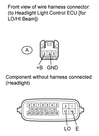
Disconnect the B1*1 or B11*2 headlight connector.
-
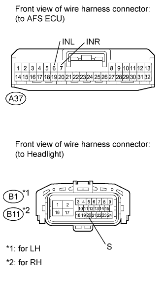
*1: for LH
-
*2: for RH
-
-
Measure the resistance according to the value(s) in the table below.
Standard Resistance for LH Tester Connection Condition Specified Condition B1-20 (S) - A37-6 (INL) Always Below 1 Ω B1-20 (S) - Body ground Always 10 kΩ or higher for RH Tester Connection Condition Specified Condition B11-20 (S) - A37-7 (INR) Always Below 1 Ω B11-20 (S) - Body ground Always 10 kΩ or higher
NG 
REPAIR OR REPLACE HARNESS OR CONNECTOR
OK
-
-
INSPECT HEADLIGHT ASSEMBLY
-
Remove the headlight Click here.
-
Disconnect the headlight light control ECU (for LO/HI beam) connector Click here.
-
Measure the resistance according to the value(s) in the table below.
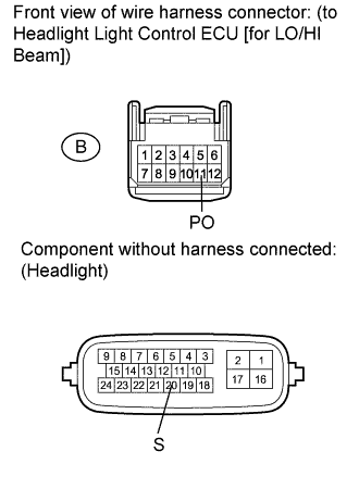
Standard Resistance Tester Connection Condition Specified Condition 20 (S) - B-11 (PO) Always Below 1 Ω
NG
REPLACE HEADLIGHT ASSEMBLY Click here
OK
-
-
CHECK HEADLIGHT LIGHT CONTROL ECU SUB-ASSEMBLY (FOR LO/HI BEAM)
-
Temporarily replace the headlight light control ECU (for LO/HI beam) with a new or normally functioning one Click here.
-
Turn the power switch on (IG).
-
Turn on the low beam headlights and high beam headlights by operating the headlight dimmer switch.
-
Check for DTC Click here.
OK DTC B2430 or B2431 output does not occur
NG
REPLACE AFS ECU Click here
OK 
END (HEADLIGHT LIGHT CONTROL ECU [FOR LO/HI BEAM] WAS DEFECTIVE)
-
-
PERFORM ACTIVE TEST USING GTS (HEADLIGHT LOW)
-
Using the GTS, perform the Active Test Click here.
Body No. 5 Tester Display Test Part Control Range Head Light Low Low beam headlight illumination operation OFF - ON OK Low beam headlight illumination condition is switched by Active Test
NG
CHECK MULTIPLEX NETWORK FRONT LIGHT ECU (HRLY VOLTAGE) Click here
OK
-
-
READ VALUE USING GTS (HEADLIGHT DIMMER SWITCH)
-
Using the GTS, read the Data List Click here.
Combination Switch Tester Display Measurement Item/Range Normal Condition Diagnostic Note Head Light Switch Headlight dimmer switch signal (HEAD position) / ON or OFF ON: Headlight dimmer switch HEAD position
OFF: Headlight dimmer switch OFF
- OK GTS display changes according to the switch operation
NG
INSPECT HEADLIGHT DIMMER SWITCH ASSEMBLY Click here
OK
-
-
CHECK HARNESS AND CONNECTOR (MULTIPLEX NETWORK FRONT LIGHT ECU - WINDSHIELD WIPER SWITCH)
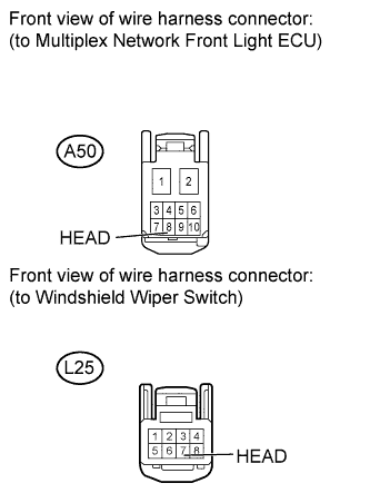
-
Disconnect the A50 multiplex network front light ECU connector.
-
Disconnect the L25 windshield wiper switch connector.
-
Measure the resistance according to the value(s) in the table below.
Standard Resistance Tester Connection Condition Specified Condition A50-8 (HEAD) - L25-7 (HEAD) Always Below 1 Ω A50-8 (HEAD) - Body ground Always 10 kΩ or higher
NG
REPAIR OR REPLACE HARNESS OR CONNECTOR
OK
-
-
CHECK WINDSHIELD WIPER SWITCH
-
Temporarily replace the windshield wiper switch with a new or normally functioning one Click here.
-
Check for DTC Click here.
OK DTC B2430 or B2431 output does not occur
NG
REPLACE MULTIPLEX NETWORK FRONT LIGHT ECU
OK
END (WINDSHIELD WIPER SWITCH WAS DEFECTIVE)
-
-
INSPECT HEADLIGHT DIMMER SWITCH ASSEMBLY
-
Remove the headlight dimmer switch Click here.
-
Inspect the headlight dimmer switch Click here.
NG
REPLACE HEADLIGHT DIMMER SWITCH ASSEMBLY Click here
OK
REPLACE WINDSHIELD WIPER SWITCH Click here
-
-
CHECK MULTIPLEX NETWORK FRONT LIGHT ECU (HRLY VOLTAGE)
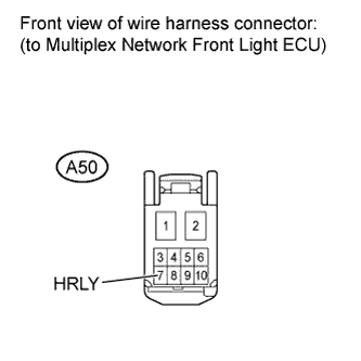
-
Disconnect the A50 multiplex network front light ECU connector.
-
Measure the voltage according to the value(s) in the table below.
Standard Voltage Tester Connection Condition Specified Condition A50-7 (HRLY) - Body ground Always 11 to 14 V
NG
CHECK HARNESS AND CONNECTOR (MULTIPLEX NETWORK FRONT LIGHT ECU - ENGINE ROOM NO. 2 RELAY BLOCK) Click here
OK
-
-
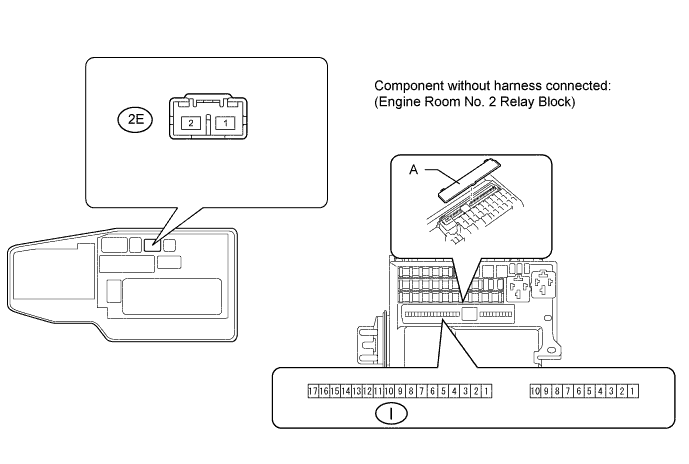
CHECK ENGINE ROOM NO. 2 RELAY BLOCK
-
Remove the cover labeled A.
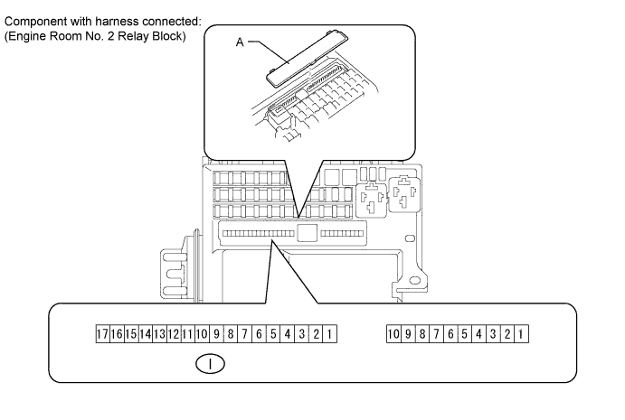
-
Measure the voltage according to the value(s) in the table below.
Standard Voltage Tester Connection Switch Condition Specified Condition I-5 - Body ground Headlight dimmer switch HEAD 11 to 14 V I-6 - Body ground Headlight dimmer switch HEAD 11 to 14 V -
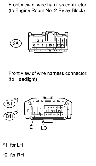
Disconnect the 2A engine room No. 2 relay block connector.
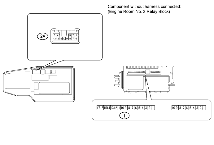
-
Measure the resistance according to the value(s) in the table below.
Standard Resistance Tester Connection Condition Specified Condition 2A-1 - I-5 Always Below 1 Ω 2A-2 - I-6 Always Below 1 Ω
NG
REPLACE ENGINE ROOM NO. 2 RELAY BLOCK
OK
-
-
CHECK HARNESS AND CONNECTOR (ENGINE ROOM NO. 2 RELAY BLOCK - HEADLIGHT)
-
Disconnect the 2A engine room No. 2 relay block connector.
-
Disconnect the B1*1 or B11*2 headlight connector.
-
*1: for LH
-
*2: for RH
-
-
Measure the resistance according to the value(s) in the table below.
Standard Resistance for LH Tester Connection Condition Specified Condition 2A-2 - B1-17 (LO) Always Below 1 Ω B1-16 (E) - Body ground Always Below 1 Ω 2A-2 - Body ground Always 10 kΩ or higher for RH Tester Connection Condition Specified Condition 2A-1 - B11-17 (LO) Always Below 1 Ω B11-16 (E) - Body ground Always Below 1 Ω 2A-1 - Body ground Always 10 kΩ or higher
NG
REPAIR OR REPLACE HARNESS OR CONNECTOR
OK
-
-
INSPECT HEADLIGHT ASSEMBLY
-
Remove the headlight Click here.
-
Disconnect the headlight light control ECU (for LO/HI beam) connector Click here.
-
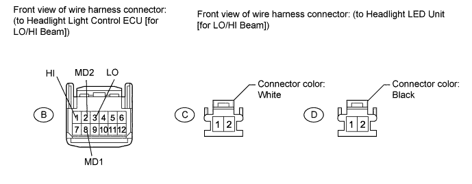
Measure the resistance according to the value(s) in the table below.
Standard Resistance Tester Connection Condition Specified Condition 17 (LO) - A-1 (+B) Always Below 1 Ω 16 (E) - A-2 (GND) Always Below 1 Ω
NG
REPLACE HEADLIGHT ASSEMBLY Click here
OK
-
-
INSPECT HEADLIGHT ASSEMBLY
-
Remove the headlight Click here.
-
Disconnect the headlight light control ECU (for LO/HI beam) connector Click here.
-
Disconnect the headlight LED unit (for LO/HI beam) connector Click here.
-
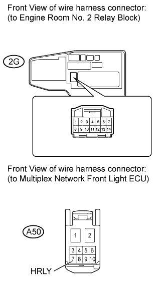
Measure the resistance according to the value(s) in the table below.
Standard Resistance Tester Connection Condition Specified Condition B-2 (MD2) - C-2 Always Below 1 Ω B-3 (LO) - C-1 Always Below 1 Ω B-1 (HI) - D-2 Always Below 1 Ω B-8 (MD1) - D-1 Always Below 1 Ω
NG
REPLACE HEADLIGHT ASSEMBLY Click here
OK
-
-
CHECK HEADLIGHT LIGHT CONTROL ECU SUB-ASSEMBLY (FOR LO/HI BEAM)
-
Temporarily replace the headlight light control ECU (for LO/HI beam) with a new or normally functioning one Click here.
-
Turn the power switch on (IG).
-
Turn on the low beam headlights and high beam headlights by operating the headlight dimmer switch.
-
Check for DTC Click here.
OK DTC B2430 or B2431 output does not occur
NG
REPLACE HEADLIGHT LED UNIT (FOR LO/HI BEAM) Click here
OK
END (HEADLIGHT LIGHT CONTROL ECU [FOR LO/HI BEAM] WAS DEFECTIVE)
-
-
CHECK HARNESS AND CONNECTOR (MULTIPLEX NETWORK FRONT LIGHT ECU - ENGINE ROOM NO. 2 RELAY BLOCK)
-
Disconnect the A50 multiplex network front light ECU connector.
-
Disconnect the 2G engine room No. 2 relay block connector.
-
Measure the resistance according to the value(s) in the table below.
Standard Resistance Tester Connection Condition Specified Condition A50-7 (HRLY) - 2G-6 Always Below 1 Ω A50-7 (HRLY) - Body ground Always 10 kΩ or higher
NG
REPAIR OR REPLACE HARNESS OR CONNECTOR
OK
-
-
CHECK ENGINE ROOM NO. 2 RELAY BLOCK

-
Remove the cover labeled A.
-
Measure the voltage according to the value(s) in the table below.
Standard Voltage Tester Connection Condition Specified Condition I-1 - Body ground Always 11 to 14 V
NG
INSPECT ENGINE ROOM NO. 2 RELAY BLOCK Click here
OK
REPLACE ENGINE ROOM NO. 2 RELAY BLOCK
-
-
INSPECT ENGINE ROOM NO. 2 RELAY BLOCK
-
Remove the cover labeled A.
-
Disconnect the 2E relay block connector.
-
Measure the resistance according to the value(s) in the table below.
Standard Resistance Tester Connection Condition Specified Condition 2E-2 - I-1 Always Below 1 Ω
NG
REPLACE ENGINE ROOM NO. 2 RELAY BLOCK
OK
REPAIR OR REPLACE HARNESS OR CONNECTOR (BATTERY - ENGINE ROOM NO. 2 RELAY BLOCK)
-