LIGHTING SYSTEM TERMINALS OF ECU

-
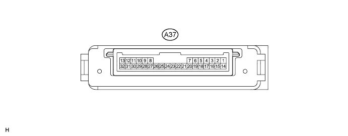
CHECK AFS ECU
-
Disconnect the A37 AFS ECU connector.
-
Measure the voltage and resistance according to the value(s) in the table below.
Terminal No. (Symbol) Wiring Color Terminal Description Condition Specified Condition A37-14 (IGS) - A37-22 (E1) GR - W-B Ignition power supply Power switch on (IG) 11 to 14 V Power switch off Below 1 Ω A37-15 (IG) - A37-22 (E1) Y - W-B Ignition power supply Power switch on (IG) 11 to 14 V Power switch off Below 1 Ω A37-22 (E1) - Body ground W-B - Body ground Ground Always Below 1 Ω
-
If the result is not as specified, there may be a malfunction on the wire harness side.
-
-
Reconnect the A37 AFS ECU connector.
-
Measure the voltage and resistance according to the value(s) in the table below.
Terminal No. (Symbol) Wiring Color Terminal Description Condition Specified Condition A37-1 (SMBL) - A37-22 (E1) L - W-B Headlight swivel motor LH power output Power switch on (IG) 11 to 14 V A37-2 (SMBR) - A37-22 (E1) L - W-B Headlight swivel motor RH power output Power switch on (IG) 11 to 14 V A37-6 (INL) - A37-22 (E1) P - W-B LO/HI beam circuit Power switch on (IG)
Low beam headlight LH illuminated
Pulse generation A37-7 (INR) - A37-22 (E1) V - W-B LO/HI beam circuit Power switch on (IG)
Low beam headlight RH illuminated
Pulse generation A37-8 (LCH) - A37-22 (E1)* B - W-B CAN communication Power switch on (IG) Pulse generation A37-9 (LCL) - A37-22 (E1)* W - W-B CAN communication Power switch on (IG) Pulse generation A37-10 (SMR) - A37-22 (E1) L - W-B Headlight swivel motor RH Power switch on (IG) Pulse generation A37-11 (RH+) - A37-22 (E1) P - W-B Headlight swivel motor RH (leveling portion) Power switch on (IG) Pulse generation A37-12 (CANH) - A37-22 (E1) B - W-B CAN communication Power switch on (IG) Pulse generation A37-13 (CANL) - A37-22 (E1) W - W-B CAN communication Power switch on (IG) Pulse generation A37-17 (SHFL) - A37-22 (E1) L - W-B Vehicle height signal Power switch on (IG) (no passengers, no luggage, vehicle not moving) Approximately 2.5 V A37-18 (SBR) - A37-22 (E1) BR - W-B Vehicle height signal Power switch on (IG) Approximately 5 V A37-19 (SHRL) - A37-22 (E1) LG - W-B Vehicle height signal Power switch on (IG) (no passengers, no luggage, vehicle not moving) Approximately 2.5 V A37-21 (SGR) - A37-22 (E1) GR - W-B Vehicle height signal Always Below 1 Ω A37-27 (LH-) - A37-22 (E1) BE - W-B Headlight swivel motor LH Always Below 1 Ω A37-28 (RH-) - A37-22 (E1) BE - W-B Headlight swivel motor RH Always Below 1 Ω A37-29 (SML) - A37-22 (E1) L - W-B Headlight swivel motor LH Power switch on (IG) Pulse generation A37-30 (LH+) - A37-22 (E1) W - W-B Headlight swivel motor LH (leveling portion) Power switch on (IG) Pulse generation
-
*: w/ Adaptive High Beam System
-
-
-
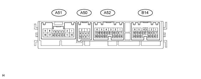
CHECK MULTIPLEX NETWORK FRONT LIGHT ECU (FRONT CONTROLLER)
-
Disconnect the A50 and A52 multiplex network front light ECU connectors.
-
Measure the voltage and resistance according to the value(s) in the table below.
Terminal No. (Symbol) Wiring Color Terminal Description Condition Specified Condition A52-1 (BATB) - A50-2 (E) P - W-B Battery power supply Always 11 to 14 V A52-5 (ALTB) - A50-2 (E) L - W-B Battery power supply Always 11 to 14 V A50-1 (FMB3) - A50-2 (E) LG - W-B Battery power supply Always 11 to 14 V A50-2 (E) - Body ground W-B - Body ground Ground Always Below 1 Ω A50-5 (FMIG) - A50-2 (E) Y - W-B Ignition power supply Power switch on (IG) 11 to 14 V Power switch off Below 1 V
-
If the result is not as specified, there may be a malfunction on the wire harness side.
-
-
Reconnect the A50 and A52 multiplex network front light ECU connectors.
-
Measure the voltage according to the value(s) in the table below.
Terminal No. (Symbol) Wiring Color Terminal Description Condition Specified Condition B14-5 (HLHR) - A50-2 (E)*1 L - W-B High beam circuit Headlight dimmer switch HEAD, low position → High position Below 1 V → 11 to 14 V B14-6 (HLHL) - A50-2 (E)*1 G - W-B High beam circuit Headlight dimmer switch HEAD, Low → High position Below 1 V → 11 to 14 V B14-15 (CRAR) - A50-2 (E) Y - W-B Taillight circuit Headlight dimmer switch OFF → TAIL position Below 1 V → 11 to 14 V B14-23 (CRAL) - A50-2 (E) P - W-B Taillight circuit Headlight dimmer switch OFF → TAIL position Below 1 V → 11 to 14 V A50-3 (CANP) - A50-2 (E) B - W-B CAN communication Power switch on (IG) Pulse generation A50-4 (CANN) - A50-2 (E) W - W-B CAN communication Power switch on (IG) Pulse generation A50-6 (FFGO) - A50-2 (E) Y - W-B Front light circuit Headlight dimmer switch (Fr FOG) OFF → ON 11 to 14 V → Below 1 V A50-7 (HRLY) - A50-2 (E) BE - W-B Low beam circuit Headlight dimmer switch OFF → HEAD position 11 to 14 V → Below 1 V A50-8 (HEAD) - A50-2 (E) R - W-B Low beam circuit Power switch on (IG)
Headlight dimmer switch OFF → HEAD position
11 to 14 V → Below 1 V A52-16 (OUT1) - A50-2 (E)*2 L - W-B High beam circuit Headlight dimmer switch HEAD, low position → High position 11 to 14 V → Below 1 V
-
*1: w/o Pre-crash Safety System
-
*2: w/o Adaptive High Beam System
-
-
-
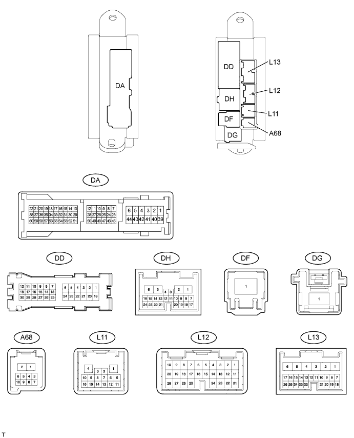
CHECK MAIN BODY ECU (DRIVER SIDE JUNCTION BLOCK ASSEMBLY)
-
Disconnect the DA, L11, L12 and L13 main body ECU connectors.
-
Measure the voltage and resistance according to the value(s) in the table below.
Terminal No. (Symbol) Wiring Color Terminal Description Condition Specified Condition DA-40 (GND2) - Body ground W-B - Body ground Ground Always Below 1 Ω L12-1 (AM2) - L11-1 (GND3) W - W-B Battery power supply Always 11 to 14 V L13-6 (AM1) - L11-1 (GND3) W - W-B Battery power supply Always 11 to 14 V L13-3 (IG1D) - L11-1 (GND3) V - W-B Ignition power supply Power switch on (IG) 11 to 14 V Power switch off Below 1 V L13-22 (ACCD) - L11-1 (GND3) G - W-B ACC power supply Power switch on (ACC) 11 to 14 V Power switch off Below 1 V
-
If the result is not as specified, there may be a malfunction on the wire harness side.
-
-
Reconnect the DA, L11, L12 and L13 main body ECU connectors.
-
Measure the voltage and resistance according to the value(s) in the table below.
Terminal No. (Symbol) Wiring Color Terminal Description Condition Specified Condition DA-33 (CIL-) - L11-1 (GND3) LG - W-B Clock illumination signal Clock illumination off → on 11 to 14 V → Below 1 V DA-55 (TRNL) - L11-1 (GND3) P - W-B LH side turn signal Headlight dimmer switch (TURN L) OFF → ON 9 V or higher → Below 1 V DA-56 (TRNR) - L11-1 (GND3) L - W-B RH side turn signal Headlight dimmer switch (TURN R) OFF → ON 9 V or higher → Below 1 V DD-12 (LCTY) - L11-1 (GND3) L - W-B Illumination signal Rear left door closed → opened 11 to 14 V → Below 1 V DF-1 (ALTB) - L11-1 (GND3) B - W-B Battery power supply Always 11 to 14 V L11-1 (GND3) - Body ground W-B - Body ground Ground Always Below 1 Ω L11-9 (SPD) - L11-1 (GND3) V - W-B Vehicle speed signal While vehicle is driven at 30 km/h (18 mph) Pulse generation (see waveform 1) L11-7 (HZSW) - L11-1 (GND3) R - W-B Hazard signal Hazard warning signal switch OFF → ON Below 1 V → 11 to 14 V L11-6 (CANL) - L11-1 (GND3) G - W-B CAN communication Power switch on (IG) Pulse generation L11-5 (CANH) - L11-1 (GND3) R - W-B CAN communication Power switch on (IG) Pulse generation L11-16 (CANP) - L11-1 (GND3) B - W-B CAN communication Power switch on (IG) Pulse generation L11-15 (CANN) - L11-1 (GND3) W - W-B CAN communication Power switch on (IG) Pulse generation L11-14 (HAZ) - L11-1 (GND3) BE - W-B Hazard signal Hazard warning signal switch OFF → ON Below 1 V → 11 to 14 V L11-11 (FSPT) - L11-1 (GND3) V - W-B Illumination signal Front and rear interior foot lights off → illuminated 11 to 14 V → Below 1 V L11-12 (ADIM) - L11-1 (GND3) G - W-B Clock illumination signal Headlight dimmer switch OFF → TAIL position Below 1 V → 11 to 14 V L12-8 (PANL) - L11-1 (GND3) GR - W-B Illumination signal Headlight dimmer switch OFF → TAIL position 11 to 14 V → Below 1 V L12-7 (RCTY) - L11-1 (GND3) R - W-B Illumination signal Rear right door closed → opened 11 to 14 V → Below 1 V L12-18 (CLTE) - Body ground W - Body ground Automatic light control sensor ground circuit Always Below 1 Ω L12-19 (CLTS) - L11-1 (GND3) V - W-B Automatic light control sensor ground circuit Power switch on (IG), headlight dimmer switch AUTO, automatic light control sensor covered by lightproof object → not covered by lightproof object Pulse generation (Waveform of "Below 1 V → Approximately 7 V → Below 1 V" is displayed; waveform varies depending on light) L12-20 (CLTB) - L11-1 (GND3) BE - W-B Automatic light control sensor power source circuit Power switch on (IG) 11 to 14 V L12-21 (PCTY) - L11-1 (GND3) L - W-B Illumination signal Front passenger door closed → opened 11 to 14 V → Below 1 V L12-14 (PIL1) - L11-1 (GND3) V - W-B Instrument panel illumination signal Instrument panel illumination is off (when not in sleep mode [20 minutes within opening any door]) Pulse generation (see waveform 2) L12-15 (PIL2) - L11-1 (GND3) G - W-B Instrument panel illumination signal Instrument panel illumination is off (when not in sleep mode [20 minutes within opening any door]) Pulse generation (see waveform 3) L12-26 (PIL3) - L11-1 (GND3) P - W-B Instrument panel illumination signal Instrument panel illumination is off (when not in sleep mode [20 minutes within opening any door]) Pulse generation (see waveform 4) L12-4 (PIL4) - L11-1 (GND3) SB - W-B Instrument panel illumination signal Instrument panel illumination is off (when not in sleep mode [20 minutes within opening any door]) Pulse generation (see waveform 5) L12-5 (PIL5) - L11-1 (GND3) GR - W-B Instrument panel illumination signal Instrument panel illumination is off (when not in sleep mode [20 minutes within opening any door]) Below 1 V → 11 to 14 V L13-24 (DCTY) - L11-1 (GND3) W - W-B Illumination signal Driver door open → closed 11 to 14 V → Below 1 V L13-25 (SWIL) - L11-1 (GND3) R - W-B Illumination signal
-
Illuminated entry control lights off → illuminated
-
Headlight dimmer switch OFF → TAIL position
Below 1 V → 11 to 14 V -
-
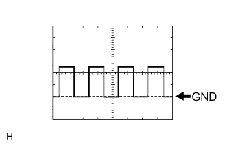
Using an oscilloscope, check the signal waveform of the ECU.
Waveform 1 Item Content Terminal No. (Symbol) L11-9 (SPD) - L11-1 (GND3) Tool Setting 5 V/DIV., 20 ms/DIV. Condition While vehicle is driven at 30 km/h (18 mph) -
Using an oscilloscope, check the signal waveform of the ECU.

Waveform 2 Item Content Terminal No. (Symbol) L12-14 (PIL1) - L11-1 (GND3) Tool Setting 2 V/DIV., 5 ms/DIV. Condition Instrument panel illumination is off (when not in sleep mode [20 minutes within opening any door]) Waveform 3 Item Content Terminal No. (Symbol) L12-15 (PIL2) - L11-1 (GND3) Tool Setting 2 V/DIV., 5 ms/DIV. Condition Instrument panel illumination is off (when not in sleep mode [20 minutes within opening any door]) Waveform 4 Item Content Terminal No. (Symbol) L12-26 (PIL3) - L11-1 (GND3) Tool Setting 2 V/DIV., 5 ms/DIV. Condition Instrument panel illumination is off (when not in sleep mode [20 minutes within opening any door]) Waveform 5 Item Content Terminal No. (Symbol) L12-4 (PIL4) - L11-1 (GND3) Tool Setting 2 V/DIV., 5 ms/DIV. Condition Instrument panel illumination is off (when not in sleep mode [20 minutes within opening any door])
-
-
CHECK LUGGAGE ROOM JUNCTION BLOCK ASSEMBLY (REAR JUNCTION BLOCK ECU)

-
Disconnect the LA, LH and LD luggage room junction block assembly connectors.
-
Measure the voltage and resistance according to the value(s) in the table below.
Terminal No. (Symbol) Wiring Color Terminal Description Condition Specified Condition LH-1 - Body ground B - Body ground Battery power supply Always 11 to 14 V LD-4 - Body ground R - Body ground Battery power supply Always 11 to 14 V LA-29 (SG) - Body ground W-B - Body ground Ground Always Below 1 Ω LA-43 (PGND) - Body ground W-B - Body ground Ground Always Below 1 Ω
-
If the result is not as specified, there may be a malfunction on the wire harness side.
-
-
Reconnect the LA, LH and LD luggage room junction block assembly connectors.
-
Measure the voltage according to the value(s) in the table below.
Terminal No. (Symbol) Wiring Color Terminal Description Condition Specified Condition S64-3 (TIL2) - LA-43 (PGND) BR - W-B Taillight circuit Headlight dimmer switch OFF → TAIL position Below 1 V → 11 to 14 V S64-7 (TIL1) - LA-43 (PGND) BR - W-B Taillight circuit Headlight dimmer switch OFF → TAIL position Below 1 V → 11 to 14 V S64-9 (STP2) - LA-43 (PGND) L - W-B Stop light switch signal Brake pedal not depressed → depressed Below 1 V → 11 to 14 V S64-10 (STP1) - LA-43 (PGND) L - W-B Stop light switch signal Brake pedal not depressed → depressed Below 1 V → 11 to 14 V S63-1 (BCK1) - LA-43 (PGND) R - W-B Back-up light signal Shift lever not on R → on R Below 1 V → 11 to 14 V S63-4 (STP3) - LA-43 (PGND) R - W-B Stop light switch signal Brake pedal not depressed → depressed Below 1 V → 11 to 14 V S63-11 (LGLP) - LA-43 (PGND) B - W-B Illumination signal Luggage compartment door closed → opened Below 1 V → 11 to 14 V S63-13 (TIL4) - LA-43 (PGND) R - W-B Taillight circuit Headlight dimmer switch OFF → TAIL position Below 1 V → 11 to 14 V S63-14 (TIL3) - LA-43 (PGND) BR - W-B Taillight circuit Headlight dimmer switch OFF → TAIL position Below 1 V → 11 to 14 V S63-15 (LCE2) - LA-43 (PGND) V - W-B Taillight circuit Headlight dimmer switch OFF → TAIL position Below 1 V → 11 to 14 V S62-6 (STP4) - LA-43 (PGND) B - W-B Stop light switch signal Brake pedal not depressed → depressed Below 1 V → 11 to 14 V S62-8 (LGCY) - LA-43 (PGND) GR - W-B Illumination signal Luggage compartment door closed → opened Below 1 V → 11 to 14 V S62-9 (LIN) - LA-43 (PGND) L - W-B LIN communication Power switch on (IG) Pulse generation S62-13 (PBIL) - LA-43 (PGND) R - W-B*1
P - W-B*2
Illumination signal Front seat inner belt illumination off → illuminated Below 1 V → 11 to 14 V S62-16 (STOP) - LA-43 (PGND) G - W-B Stop light switch signal Brake pedal not depressed → depressed Below 1 V → 11 to 14 V S62-24 (RBI2) - LA-43 (PGND)*3 R - W-B*4
LG - W-B*5
Illumination signal Rear seat inner belt illumination off → illuminated Below 1 V → 11 to 14 V S62-20 (CANP) - LA-43 (PGND) B - W-B CAN communication Power switch on (IG) Pulse generation S62-28 (CANN) - LA-43 (PGND) W - W-B CAN communication Power switch on (IG) Pulse generation S61-21 (DBIL) - LA-43 (PGND) P - W-B*1
R - W-B*2
Illumination signal Front seat inner belt illumination off → illuminated Below 1 V → 11 to 14 V S61-20 (RBIL) - LA-43 (PGND)*3 B - W-B Illumination signal Rear seat inner belt illumination off → illuminated Below 1 V → 11 to 14 V
-
*1: for LHD
-
*2: for RHD
-
*3: w/ Rear Seat Inner Belt illumination
-
*4: w/ Rear Power Seat Control System
-
*5: w/o Rear Power Seat Control System
-
-
-
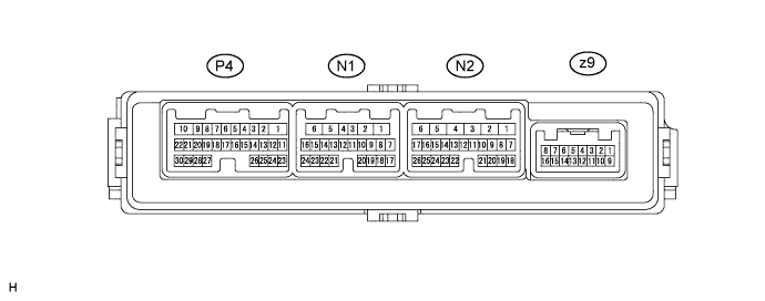
CHECK FRONT MULTIPLEX NETWORK DOOR ECU RH
-
Disconnect the N1 front multiplex network door ECU RH connector.
-
Measure the voltage and resistance according to the value(s) in the table below.
Terminal No. (Symbol) Wiring Color Terminal Description Condition Specified Condition N1-3 (SIG) - Body ground V - Body ground*1
L - Body ground*2
Ignition power supply Power switch on (IG) 11 to 14 V Power switch off Below 1 V N1-6 (BDR) - Body ground BE - Body ground Battery power supply Always 11 to 14 V N1-11 (CPUB) - Body ground R - Body ground*1
B - Body ground*2
Battery power supply Always 11 to 14 V N1-16 (BDG1) - Body ground R - Body ground Battery power supply Always 11 to 14 V N1-1 (GND) - Body ground W-B - Body ground Ground Always Below 1 Ω
-
*1: for LHD
-
*2: for RHD
-
If the result is not as specified, there may be a malfunction on the wire harness side.
-
-
Reconnect the N1 front multiplex network door ECU RH connector.
-
Measure the voltage according to the value(s) in the table below.
Terminal No. (Symbol) Wiring Color Terminal Description Condition Specified Condition P4-6 (CTYB) - P4-7 (CYL) LG - L Illumination signal Front RH door closed → opened Below 1 V → 11 to 14 V P4-10 (LED+) - P4-22 (LED-) B - R Illumination signal Inside handle illumination off → illuminated (based on inside handle illumination control) Below 1 V → 11 to 14 V N1-9 (CANP) - N1-1 (GND) R - W-B CAN communication Power switch on (IG) Pulse generation N1-10 (CANN) - N1-1 (GND) W - W-B CAN communication Power switch on (IG) Pulse generation z9-2 (LP) - z9-12 (HTR-) LG - W Illumination signal Door mirror foot light RH off → illuminated (based on door mirror foot light control) Below 1 V → 11 to 14 V
-
-
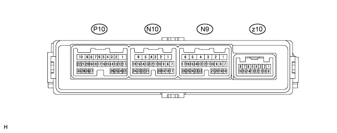
CHECK FRONT MULTIPLEX NETWORK DOOR ECU LH
-
Disconnect the N10 front multiplex network door ECU LH connector.
-
Measure the voltage and resistance according to the value(s) in the table below.
Terminal No. (Symbol) Wiring Color Terminal Description Condition Specified Condition N10-3 (SIG) - Body ground L - Body ground*1
V - Body ground*2
Ignition power supply Power switch on (IG) 11 to 14 V Power switch off Below 1 V N10-6 (BDR) - Body ground BE - Body ground Battery power supply Always 11 to 14 V N10-11 (CPUB) - Body ground B - Body ground*1
R - Body ground*2
Battery power supply Always 11 to 14 V N10-16 (BDG1) - Body ground R - Body ground Battery power supply Always 11 to 14 V N10-1 (GND) - Body ground W-B - Body ground Ground Always Below 1 Ω
-
*1: for LHD
-
*2: for RHD
-
If the result is not as specified, there may be a malfunction on the wire harness side.
-
-
Reconnect the N10 front multiplex network door ECU LH connector.
-
Measure the voltage according to the value(s) in the table below.
Terminal No. (Symbol) Wiring Color Terminal Description Condition Specified Condition P10-6 (CTYB) - P10-7 (CYL) LG - L Illumination signal Front LH door closed → opened Below 1 V → 11 to 14 V P10-10 (LED+) - P10-22 (LED-) B - R Illumination signal Inside handle illumination off → illuminated (based on inside handle illumination control) Below 1 V → 11 to 14 V N10-9 (CANP) - N10-1 (GND) R - W-B CAN communication Power switch on (IG) Pulse generation N10-10 (CANN) - N10-1 (GND) W - W-B CAN communication Power switch on (IG) Pulse generation z10-2 (LP) - z10-12 (HTR-) LG - W Illumination signal Door mirror foot light LH off → illuminated (based on door mirror foot light control) Below 1 V → 11 to 14 V
-
-
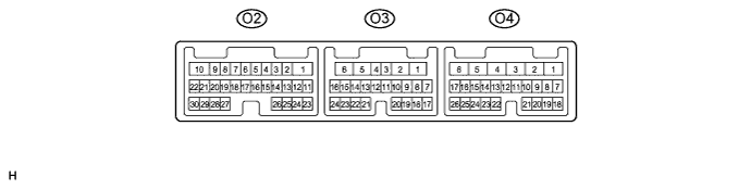
CHECK REAR MULTIPLEX NETWORK DOOR ECU RH
-
Disconnect the O3 rear multiplex network door ECU RH connector.
-
Measure the voltage and resistance according to the value(s) in the table below.
Terminal No. (Symbol) Wiring Color Terminal Description Condition Specified Condition O3-3 (SIG) - Body ground GR - Body ground Ignition power supply Power switch on (IG) 11 to 14 V Power switch off Below 1 V O3-6 (BDR) - Body ground L - Body ground Battery power supply Always 11 to 14 V O3-11 (CPUB) - Body ground R - Body ground Battery power supply Always 11 to 14 V O3-1 (GND) - Body ground W-B - Body ground Ground Always Below 1 Ω
-
If the result is not as specified, there may be a malfunction on the wire harness side.
-
-
Reconnect the O3 rear multiplex network door ECU RH connector.
-
Measure the voltage according to the value(s) in the table below.
Terminal No. (Symbol) Wiring Color Terminal Description Condition Specified Condition O2-6 (CTYB) - O2-7 (CYL) LG - L Illumination signal Rear right door closed → opened Below 1 V → 11 to 14 V O2-11 (LED+) - O2-12 (LED-) B - R Illumination signal Inside handle illumination off → illuminated (based on inside handle illumination control) Below 1 V → 11 to 14 V O2-16 (ASH+) - O2-15 (ASH-) P - GR Illumination signal Rear ashtray light RH off → illuminated Below 1 V → 11 to 14 V O3-9 (CANP) - O3-1 (GND) R - W-B CAN communication Power switch on (IG) Pulse generation O3-10 (CANN) - O3-1 (GND) W - W-B CAN communication Power switch on (IG) Pulse generation
-
-
CHECK REAR MULTIPLEX NETWORK DOOR ECU LH

-
Disconnect the O14 rear multiplex network door ECU LH connector.
-
Measure the voltage and resistance according to the value(s) in the table below.
Terminal No. (Symbol) Wiring Color Terminal Description Condition Specified Condition O14-3 (SIG) - Body ground Y - Body ground Ignition power supply Power switch on (IG) 11 to 14 V Power switch off Below 1 V O14-6 (BDR) - Body ground L - Body ground Battery power supply Always 11 to 14 V O14-11 (CPUB) - Body ground R - Body ground Battery power supply Always 11 to 14 V O14-1 (GND) - Body ground W-B - Body ground Ground Always Below 1 Ω
-
If the result is not as specified, there may be a malfunction on the wire harness side.
-
-
Reconnect the O14 rear multiplex network door ECU LH connector.
-
Measure the voltage according to the value(s) in the table below.
Terminal No. (Symbol) Wiring Color Terminal Description Condition Specified Condition O15-6 (CTYB) - O15-7 (CYL) LG - L Illumination signal Rear left door closed → opened Below 1 V → 11 to 14 V O15-11 (LED+) - O15-12 (LED-) B - R Illumination signal Inside handle illumination off → illuminated (based on inside handle illumination control) Below 1 V → 11 to 14 V O15-16 (ASH+) - O15-15 (ASH-) P - GR Illumination signal Rear ashtray light LH off → illuminated Below 1 V → 11 to 14 V O14-9 (CANP) - O14-1 (GND) R - W-B CAN communication Power switch on (IG) Pulse generation O14-10 (CANN) - O14-1 (GND) W - W-B CAN communication Power switch on (IG) Pulse generation
-
-
CHECK WINDSHIELD WIPER SWITCH

-
Disconnect the L25 windshield wiper switch connector.
-
Measure the voltage and resistance according to the value(s) in the table below.
Terminal No. (Symbol) Wiring Color Terminal Description Condition Specified Condition L25-1 (B) - Body ground B - Body ground Battery power supply Always 11 to 14 V L25-2 (IG) - Body ground G - Body ground Ignition power supply Power switch on (IG) 11 to 14 V Power switch off Below 1 V L25-8 (E) - Body ground W-B - Body ground Ground Always Below 1 Ω
-
If the result is not as specified, there may be a malfunction on the wire harness side.
-
-
Reconnect the L25 windshield wiper switch connector.
-
Measure the voltage according to the value(s) in the table below.
Terminal No. (Symbol) Wiring Color Terminal Description Condition Specified Condition L25-5 (CANP) - L25-8 (E) P - W-B CAN communication Power switch on (IG) Pulse generation L25-6 (CANN) - L25-8 (E) V - W-B CAN communication Power switch on (IG) Pulse generation L25-7 (HEAD) - L25-8 (E) R - W-B Low beam circuit Headlight dimmer switch OFF → HEAD position Below 1 V → 11 to 14 V
-
-
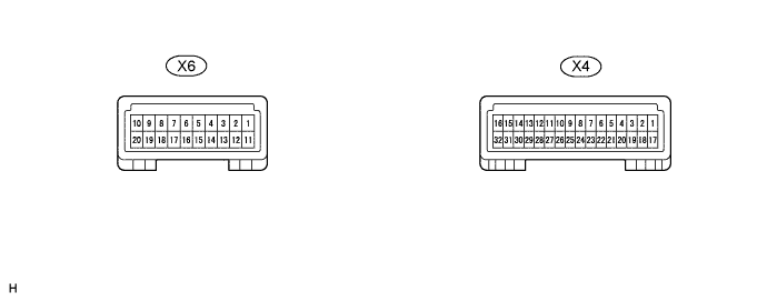
CHECK MAP LIGHT ASSEMBLY
-
Disconnect the X4 and X6 map light assembly connectors.
-
Measure the voltage and resistance according to the value(s) in the table below.
Terminal No. (Symbol) Wiring Color Terminal Description Condition Specified Condition X4-6 (+B) - Body ground B - Body ground Battery power supply Always 11 to 14 V X4-27 (DOME) - Body ground GR - Body ground Battery power supply Always 11 to 14 V X4-9 (IG) - Body ground L - Body ground Ignition power supply Power switch on (IG) 11 to 14 V Power switch off Below 1 V X4-16 (GND9) - Body ground W-B - Body ground Ground Always Below 1 Ω X6-20 (GND4) - Body ground W-B - Body ground Ground Always Below 1 Ω
-
If the result is not as specified, there may be a malfunction on the wire harness side.
-
-
Reconnect the X4 and X6 map light assembly connectors.
-
Measure the voltage and resistance according to the value(s) in the table below.
Terminal No. (Symbol) Wiring Color Terminal Description Condition Specified Condition X4-3 (RLSW) - X4-16 (GND9) V - W-B RR spot light circuit RR spot light switch OFF → ON Below 1 V → 11 to 14 V X4-4 (RRSW) - X4-16 (GND9) P - W-B RL spot light circuit RL spot light switch OFF → ON Below 1 V → 11 to 14 V X4-10 (+B1) - X4-16 (GND9) L - W-B Battery power supply Always 11 to 14 V X4-11 (ILLB) - X4-16 (GND9) R - W-B Battery power supply Always 11 to 14 V X4-12 (RLVS) - X4-16 (GND9) V - W-B RL vanity light circuit RL vanity light switch OFF → ON Below 1 V → 11 to 14 V X4-13 (RRVS) - X4-16 (GND9) V - W-B RR vanity light circuit RR vanity light switch OFF → ON Below 1 V → 11 to 14 V X4-15 (GND6) - X4-16 (GND9) G - W-B Ground Always Below 1 Ω X4-26 (+B2) - X4-16 (GND9) L - W-B Battery power supply Always 11 to 14 V X4-28 (FVT) - X4-16 (GND9) W - W-B Vanity light circuit Visor assembly (vanity light switch ON) (battery saver not operating) → visor assembly (vanity light switch ON) (battery saver operating) Below 1 V → 11 to 14 V X6-2 (LIN) - X4-16 (GND9) L - W-B LIN communication Power switch on (IG) Pulse generation X6-7 (RLMP) - X4-16 (GND9) W - W-B RL spot light circuit Always 11 to 14 V X6-8 (RRMP) - X4-16 (GND9) B - W-B RR spot light circuit Always 11 to 14 V X6-11 (ILL+) - X4-16 (GND9) G - W-B ACC power supply Power switch on (ACC) 11 to 14 V X6-13 (ILL-) - X4-16 (GND9) LG - W-B Illumination signal
-
Power switch on (ACC)
-
Headlight dimmer switch OFF → TAIL position
11 to 14 V → Below 1 V X6-14 (RRVT) - X4-16 (GND9) B - W-B RR vanity light circuit RR vanity light switch OFF → ON 11 to 14 V → Below 1 V X6-15 (RIL-) - X4-16 (GND9) BR - W-B Room light switch illumination circuit Room light switch illumination off → illuminated 11 to 14 V → Below 1 V X6-16 (RLVT) - X4-16 (GND9) B - W-B RL vanity light circuit RL vanity light switch OFF → ON 11 to 14 V → Below 1 V X6-18 (RILL) - X4-16 (GND9) L - W-B Rear dome light circuit Rear dome light off → illuminated (based on rear door light control) 11 to 14 V → Below 1 V -
-
-
CHECK INNER REAR VIEW MIRROR ASSEMBLY (AUTOMATIC HIGH BEAM SENSOR) (w/ Automatic High Beam System)

-
Disconnect the X21 inner rear view mirror assembly connector.
-
Measure the voltage and resistance according to the value(s) in the table below.
Terminal No. (Symbol) Wiring Color Terminal Description Condition Specified Condition X21-2 (IG) - Body ground G - Body ground Ignition power supply Power switch on (IG) 11 to 14 V Power switch off Below 1 V X21-10 (E) - Body ground B - Body ground Ground Always Below 1 Ω If the result is not as specified, there may be a malfunction on the wire harness side.
-
Reconnect the X21 inner rear view mirror assembly connector.
-
Measure the voltage according to the value(s) in the table below.
Terminal No. (Symbol) Wiring Color Terminal Description Condition Specified Condition X21-5 (LIN) - X21-10 (E) BE - B LIN communication Automatic high beam system operates Pulse generation
-
-
CHECK INNER REAR VIEW MIRROR ASSEMBLY (ADAPTIVE HIGH BEAM SYSTEM SENSOR) (w/ Adaptive High Beam System)
-
Disconnect the X21 inner rear view mirror assembly connector.
-
Measure the voltage and resistance according to the value(s) in the table below.
Terminal No. (Symbol) Wiring Color Terminal Description Condition Specified Condition X21-2 (IG) - Body ground G - Body ground Ignition power supply Power switch on (IG) 11 to 14 V Power switch off Below 1 V X21-10 (E) - Body ground B - Body ground Ground Always Below 1 Ω If the result is not as specified, there may be a malfunction on the wire harness side.
-
Reconnect the X21 inner rear view mirror assembly connector.
-
Measure the voltage according to the value(s) in the table below.
Terminal No. (Symbol) Wiring Color Terminal Description Condition Specified Condition X21-8 (CANH) - X21-10 (E) B - B CAN communication Adaptive high beam system operates Pulse generation X21-9 (CANL) - X21-10 (E) W - B CAN communication Adaptive high beam system operates Pulse generation
-
-
CHECK NO. 1 INSTRUMENT PANEL GARNISH SUB-ASSEMBLY (PASSENGER SIDE INSTRUMENT PANEL ILLUMINATION)

-
Disconnect the L171 No. 1 instrument panel garnish connector.
-
Measure the voltage and resistance according to the value(s) in the table below.
Terminal No. (Symbol) Wiring Color Terminal Description Condition Specified Condition L171-11 (GND2) - Body ground W-B - Body ground Ground Always Below 1 Ω L171-14 (GND) - Body ground W-B - Body ground Ground Always Below 1 Ω L171-16 (ECUB) - Body ground R - Body ground Battery power supply Always 11 to 14 V
-
If the result is not as specified, there may be a malfunction on the wire harness side.
-
-
Reconnect the L171 No. 1 instrument panel garnish connector.
-
Measure the voltage according to the value(s) in the table below.
Terminal No. (Symbol) Wiring Color Terminal Description Condition Specified Condition L171-4 (LED+) - Body ground Y - Body ground Driver side instrument panel illumination circuit Power switch on (ACC) 7.5 to 8.5 V L171-12 (DO3) - Body ground LG - Body ground Driver side instrument panel illumination circuit Driver side instrument panel illumination illuminated Pulse generation L171-13 (DO2) - Body ground GR - Body ground Driver side instrument panel illumination circuit Driver side instrument panel illumination illuminated Pulse generation L171-5 (DOUT) - Body ground L - Body ground Driver side instrument panel illumination circuit Driver side instrument panel illumination illuminated Pulse generation L171-2 (INP1) - Body ground V - Body ground Instrument panel illumination signal Instrument panel illumination is off (when not in sleep mode [20 minutes within opening any door]) Pulse generation (see waveform 1) L171-1 (INP2) - Body ground G - Body ground Instrument panel illumination signal Instrument panel illumination is off (when not in sleep mode [20 minutes within opening any door]) Pulse generation (see waveform 2) L171-9 (INP3) - Body ground P - Body ground Instrument panel illumination signal Instrument panel illumination is off (when not in sleep mode [20 minutes within opening any door]) Pulse generation (see waveform 3) L171-10 (INP4) - Body ground SB - Body ground Instrument panel illumination signal Instrument panel illumination is off (when not in sleep mode [20 minutes within opening any door]) Pulse generation (see waveform 4) L171-7 (OUT1) - Body ground GR - Body ground Instrument panel illumination signal Instrument panel illumination is off (when not in sleep mode [20 minutes within opening any door]) → Illuminate Below 1 V → 11 to 14 V -
Using an oscilloscope, check the signal waveform of the ECU.
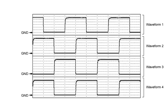
Waveform 1 Item Content Terminal No. (Symbol) L171-2 (INP1) - Body ground Tool Setting 2 V/DIV., 5 ms/DIV. Condition Instrument panel illumination is off (when not in sleep mode [20 minutes within opening any door]) Waveform 2 Item Content Terminal No. (Symbol) L171-1 (INP2) - Body ground Tool Setting 2 V/DIV., 5 ms/DIV. Condition Instrument panel illumination is off (when not in sleep mode [20 minutes within opening any door]) Waveform 3 Item Content Terminal No. (Symbol) L171-9 (INP3) - Body ground Tool Setting 2 V/DIV., 5 ms/DIV. Condition Instrument panel illumination is off (when not in sleep mode [20 minutes within opening any door]) Waveform 4 Item Content Terminal No. (Symbol) L171-10 (INP4) - Body ground Tool Setting 2 V/DIV., 5 ms/DIV. Condition Instrument panel illumination is off (when not in sleep mode [20 minutes within opening any door])
-