DRIVING SUPPORT ECU INSTALLATION

Tech Tips
A bolt without a torque specification is shown in the standard bolt chart Click here.
-
INSTALL DRIVING SUPPORT ECU ASSEMBLY
-
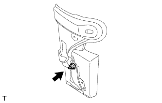
Install the driving support ECU assembly with the nut.
Note
-
Do not use a driving support ECU assembly which has been dropped or subjected to any strong shocks.
-
During the removal and installation, do not remove the drip-proof cover.
-
When a new driving support ECU assembly is installed, perform initialization.
-
-
-
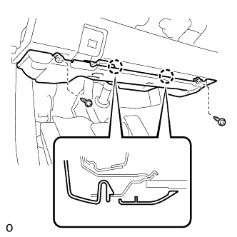
INSTALL DASH PANEL EXTENSION LH
-
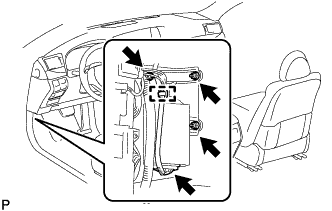
Connect the connector.
-
Install the dash panel extension LH and driving support ECU assembly as a unit with the 2 nuts and bolt.
-
Attach the wire harness clamp.
-
for RHD:
Return the floor carpet to its original position.
-
-
INSTALL NO. 3 DASH PANEL INSULATOR PAD (for LHD)
-
Install the No. 3 dash panel insulator pad.
-
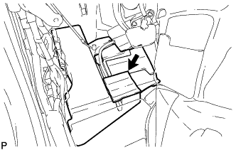
Connect the No. 2 cooler unit drain hose.
-
Clean the No. 3 dash panel insulator pad surface.
-
Attach a new No. 1 cooling unit packing in the position shown in the illustration.
-
Return the floor carpet to its original position.
-
Attach the clamp.
-
-
INSTALL ACCELERATOR PEDAL SENSOR ASSEMBLY (for LHD)
Note
-
Avoid physical shocks to the accelerator pedal sensor.
-
Do not disassemble the accelerator pedal sensor.
-
This accelerator pedal does not require lubrication.
Do not apply oil or lubricant to the accelerator pedal sensor assembly.
If it is applied, the accelerator pedal sensor assembly may not move smoothly.
-
Connect the tip of the accelerator pedal sensor to the bracket.
-
Install the accelerator pedal sensor with the 3 nuts.
- Torque:
- 5.4 N*m { 55 kgf*cm, 48 in.*lbf }
-
Connect the accelerator pedal sensor connector.
-
-
INSTALL COWL SIDE TRIM BOARD LH
-
Attach the 3 claws to install the cowl side trim board LH.
-
-
INSTALL FRONT DOOR SCUFF PLATE LH
-
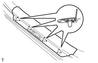
Attach the 4 clips.
-
Attach the 7 claws to install the front door scuff plate LH.
-
-
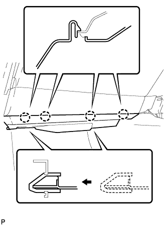
INSTALL NO. 1 INSTRUMENT PANEL UNDER COVER SUB-ASSEMBLY (for LHD)
-
Connect each connector and attach each wire harness clamp.
-
Attach the 2 claws to connect the DLC3.
-
Attach the 2 claws to install the No. 1 instrument panel under cover sub-assembly.
-
Install the 2 screws.
-
-
INSTALL NO. 2 INSTRUMENT PANEL UNDER COVER SUB-ASSEMBLY (for RHD)
-
Connect the connector.
-
Insert the 2 guides.
-
Attach the 4 claws to install the No. 2 instrument panel under cover sub-assembly.
-