OBJECT RECOGNITION ECU INSTALLATION

Note
When replacing the object recognition ECU, make sure to perform the replacement after confirming that the headlight assembly is securely installed.
-
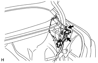
INSTALL OBJECT RECOGNITION ECU
-
Attach the 2 clips to install the object recognition ECU.
-
Install the 2 bolts.
- Torque:
- 7.4 N*m { 75 kgf*cm, 65 in.*lbf }
-
Connect the 2 connectors.
Note
Do not use an object recognition ECU which has been dropped or subjected to any strong shocks.
-
-
INSTALL LUGGAGE COMPARTMENT TRIM COVER ASSEMBLY RH
-
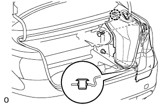
Install the luggage compartment trim cover assembly RH with the claw and 2 clips.
-
-
INSTALL REAR FLOOR FINISH PLATE
-
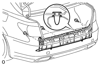
Attach the 4 clips to install the rear floor finish plate.
-
Install the 3 clips.
-
-
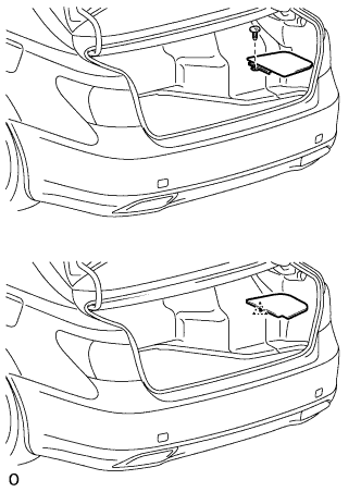
INSTALL TOOL BOX (w/o Spare Tire)
-
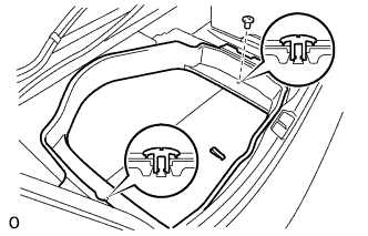
Install the tool box with the 2 clips.
-
-
INSTALL DECK BOARD ASSEMBLY (w/o Spare Tire)
-
INSTALL FRONT LUGGAGE COMPARTMENT TRIM COVER
-
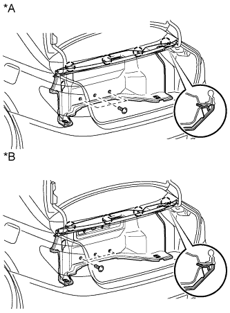
Text in Illustration *A w/o Rear Cooler *B w/ Rear Cooler Attach the 4 claws to install the front luggage compartment trim cover.
-
Install the 3 clips.
-
-
INSTALL NO. 1 COOLER COVER (w/ Rear Cooler)
-
Attach the 5 clips to install the No. 1 cooler cover.
-
-
INSTALL ROPE HOOK
-
Install the 4 rope hooks.
-
-
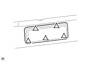
INSTALL NO. 1 LUGGAGE COMPARTMENT LIGHT ASSEMBLY
-
Connect the connector.
-
Attach the 2 claws to Install the No. 1 luggage compartment light assembly.
-
-
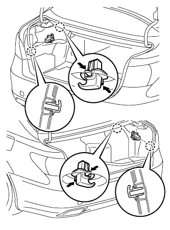
INSTALL DECK TRIM SIDE BOARD RH
-
Text in Illustration *A w/ Spare Tire *B w/o Spare Tire w/ Spare Tire:
-
Install the deck trim side board RH with the clip.
-
-
w/o Spare Tire:
-
Attach the clip to install the deck trim side board RH.
-
-
-
INSTALL ROPE HOOK ASSEMBLY
-
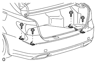
Install the 4 rope hook assemblies with the 4 bolts.
-
-
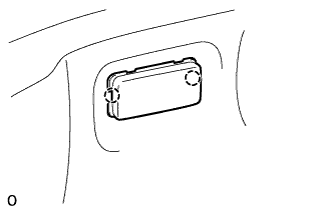
INSTALL BATTERY SERVICE HOLE COVER LH
-

Text in Illustration *A for Standard *B for Ottoman Attach the battery service hole cover LH with the clip and fastening tape.
-
-
INSTALL DECK TRIM SIDE BOARD LH (w/o Spare Tire)
-

Attach the 2 clips to install the deck trim side board LH.
-
-
INSTALL DECK BOARD ASSEMBLY (w/o Spare Tire)

-
INSTALL LUGGAGE COMPARTMENT MAT SUB-ASSEMBLY (w/ Spare Tire)

-
ADJUST OBJECT RECOGNITION CAMERA
Note
-
Make sure there are no black and white patterned objects in front of the vehicle.
-
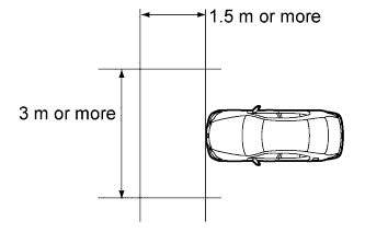
Perform the measurement in a place with no wind, and make sure there is a distance of 1.5 m (4.92 ft.) or more in front of the vehicle and that the surface is level with no obstacles.
-
Make sure that there is no wind when performing the measurement.
-
Check that there are no reflective materials in the surroundings or on the ground within a 3 m (9.84 ft.) or more x 3 m (9.84 ft.) or more area in front of the vehicle.
-
Perform the inspection in a bright area.
-
Beam axis learning preparation
-
Move the vehicle to a level surface.
-
Make sure the engine oil in the vehicle is at the specified amount.
-
Make sure the engine coolant in the vehicle is at the specified amount.
-
Make sure the fuel tank is full.
-
Make sure the spare tire is in the vehicle. (w/ Spare Tire)
-
Make sure the standard tools are in the vehicle.
-
Make sure nobody is in the vehicle.
-
Make sure no extra loads are in the vehicle.
-
Adjust the tire pressures to the specified pressure.
-
Clean the front glass.
-
If the lens of the object recognition camera sensor is dirty, apply a small amount of lens cleaner to a clean, soft cloth and clean the lens.
-
-
Perform height control sensor adjustment
-
Perform the height control sensor adjustment Click here.
Note
Perform this procedure as accurately as possible.
-
-
Perform the front wheel alignment adjustment
-
Perform the front wheel alignment adjustment Click here.
Note
Perform this procedure as accurately as possible.
-
-
Perform the rear wheel alignment adjustment
-
Perform the rear wheel alignment adjustment Click here.
Note
-
Perform this procedure as accurately as possible.
-
Press the height control switch and change the vehicle height to HIGH and return it to NORM. Then repeat.
-
-
-
Target sheet creation
-
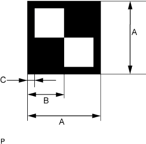
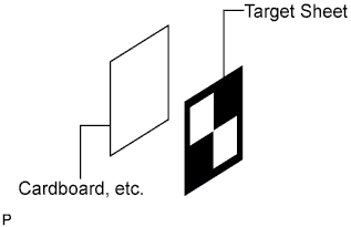
Print or copy the illustration below. Check that the dimensions are +/-5 mm (0.197 in.) of the ones in the table below.
Dimension Area Specification A 160 mm (6.30 in.) B 80 mm (3.15 in.) C 16 mm (0.630 in.) Note
-
Make sure that the black areas of the target sheets are not glossy.
-
Make sure that the borders of the black and white areas on the target sheets are straight, and are not warped or blurry.
If the print or copy's dimensions are not as specified, adjust settings and reprint or recopy so that the print or copy's dimensions are as specified.

-
-
-
Target sheet attachment
-
Place the prepared target sheet on a piece of cardboard of the same size with the black area on the top right, as shown in the illustration. Then use double-sided tape to fix the target sheet in place.
Note
Do not attach reflective tape, such as scotch tape, etc. to the target face as this may affect target recognition.
-
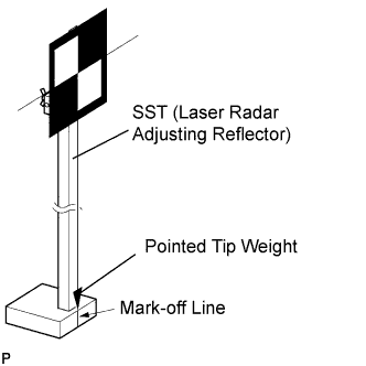
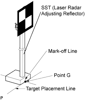
Hang a weight with a pointed tip from the center of the target sheet. Then, with double-sided tape, attach the target sheet to the reflector so that the weight aligns with the mark-off line of SST (laser radar adjusting reflector).
- SST
- 09870-60000 ( 09870-60010, 09870-60020 )
Note
-
Perform this procedure as accurately as possible.
-
Attach the target sheet so that it is horizontal with the ground.
-
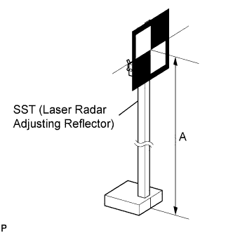
Move the reflector up and down to position the center of the target at the height shown in the illustration, and fix it in place.
Dimension A 1270 mm (4.17ft.) - SST
- 09870-60000 ( 09870-60010, 09870-60020 )
Note
Perform this procedure as accurately as possible.
-
-
Target placement point measurement
Note
-
Perform this procedure as accurately as possible.
-
Do not place reflective materials in the area behind the target.
-
Make sure there are no patterns on the wall behind the target.
-
Make sure the distance between the target and wall is within 3 m (9.84 ft.).
-
Do not place black and white patterned objects near the target.
-
Make sure the target's shadow is not on the wall, as the camera may have a recognition error.
-
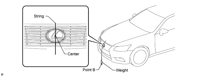
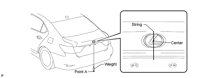
From the center of the front bumper (center of the emblem), hang a weight with a pointed tip, and mark point B on the ground.
-
From the center of the rear bumper (center of the emblem), hang a weight with a pointed tip, and mark point A on the ground.
-
Using a piece of string that uses point A as a starting point and that passes through point B, make a straight line on the ground ahead of the vehicle 2 m (6.56 ft.) or more from point B.
Tech Tips
-
Make sure to secure the string (using tape, etc.) when it is taut.
-
Lightly flick the string with your fingers several times to confirm that the string is aligned above point B.
-
-
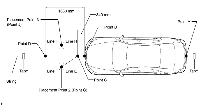
Mark point C at a position 340 mm (1.12 ft.) from point B.
-
Mark point D at a position 1660 mm (5.44 ft.) from point B.
-
Using the string, mark line E at a position 1000 mm (3.28 ft.) from point C.
-
Using the string, mark line H at a position 1000 mm (3.28 ft.) from point C.
-
Using the string, mark line F at a position 1000 mm (3.28 ft.) from point D.
-
Using the string, mark line I at a position 1000 mm (3.28 ft.) from point D.
-
Mark point G at the point where line E and line F intersect (placement point 2).
-
Mark point J at the point where line H and line I intersect (placement point 3).
-
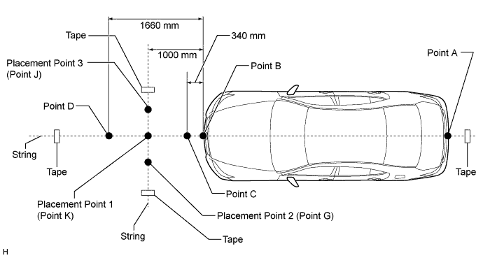
Secure a string that connects point G and point J to the ground (target placement line).
-
Mark point K at the intersection between the string connecting points C and D and the string connecting points G and J (placement point 1).
-
Confirm the distance measurements for points K, G, and J (placement points 1, 2, and 3) again.
-
-
Object recognition camera sensor height measurement
Note
-
Do not place black and white patterned objects near the target.
-
Face the vehicle toward a wall with no patterns, or make sure the background behind the target has no patterns.
-
Perform this procedure as accurately as possible.
-
Do not place reflective materials in the area behind the target.
-
Make sure there are no patterns on the wall behind the target.
-
Make sure the distance between the target and wall is within 3 m (9.84 ft.).
-
Make sure the target's shadow is not on the wall, as the camera may have a recognition error.
-
Measure the distance (X mm or in.) from the ground to point H for the front left wheel arch.
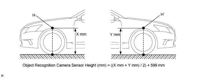
-
Measure the distance (Y mm or in.) from the ground to point H for the front right wheel arch.
-
The average of the 2 distances (X mm or in. Y mm or in.) plus 599 mm (23.6 in.) is the height of the object recognition camera sensor.
-
-
Memorize camera/target position
Note
-
Close all doors.
-
Perform the procedure with no one in the vehicle.
-
During the procedure, do not lean on the vehicle.
-
Illuminate the clearance lights.
-
Do not illuminate the headlights.
-
Connect the intelligent tester to the DLC3.
-
Turn the power switch ON (IG).*1
-
Turn the intelligent tester main switch ON.
-
Select "Auto" from the display screen and proceed to the next screen.
-
Select each option for the vehicle being adjusted from the display screen.
-
Select "Chassis" or "Body" from the display screen.
-
Select "Lane Keeping Assist" or "Pre-Crash 2" and then "Utility" from the display screen
-
Select "Camera/target position memory" from the display screen.
-
Follow the tester display, and select "Next".
-
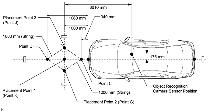
Input the measured height of the object recognition camera sensor and the horizontal position of the camera "175 mm (6.89 in.)" into the input screen. Then press the "Next" button on the display screen.
-
Input "3010 mm (119 in.)" for the distance from the camera to the target and "1270 mm (50.0 in.)" for the height of the target into the input screen. Then press the "Next" button on the display screen.
Tech Tips
When the "Next" button is pressed, a 70 second countdown begins.
-
Press the "Exit" button to finish the camera/target position memory mode.
Note
If "Error Camera/target position memory" is displayed on the screen, press the "Try Again" button, and repeat the procedures from *1 again.
-
-
Beam axis learning
-
Select "Camera axis adjust" from the display screen.*1
-
Follow the tester display, and select "Next".
-

Align the target sheet with the target placement line, and align the mark-off line with placement point 1 (point K).
-
Check that the screen displays beam axis learning for target 1, then press the "Next" button on the display screen.
Tech Tips
When the "Next" button is pressed, the buzzer sounds for 1 second.
-
Align the target sheet with the target placement line, and align the mark-off line with placement point 2 (point G).
-
Check that the screen displays beam axis learning for target 2, then press the "Next" button on the display screen.
Tech Tips
When the "Next" button is pressed, a 180 second countdown begins.
Note
Within 3 minutes after the screen displays the beam axis learning for target 2, move the target and press the "Next" button on the display screen.
-

Align the target sheet with the target placement line, and align the mark-off line with placement point 3 (point J).
-
Check that the screen displays beam axis learning for target 3, then press the "Next" button on the display screen.
Tech Tips
When the "Next" button is pressed, a 180 second countdown begins.
Note
Within 3 minutes after the screen displays the beam axis learning for target 3, move the target and press the "Next" button on the display screen.
-
Press the "Exit" button to finish the beam axis learning mode.
Note
If "Error camera axis adjust" is displayed on the screen, press the "Exit" button. Then after checking the conditions below, turn the power switch ON (IG) and OFF, and repeat from procedure *1 again.
-
Height of the target.
-
Distance from object recognition camera sensor to target.
-
Orientation of target (black area positioned on top right).
-
If surrounding area is bright enough.
-
If black and white patterned objects are placed near the target.
-
-
-