LIGHTING SYSTEM, Diagnostic DTC:B124D, B2432

| DTC Code | DTC Name |
|---|---|
| B124D | Lost Communication with AFS LIN |
| B2432 | Lost Communication with Automatic High Beam Sensor |
DESCRIPTION
-
DTC B124D is stored when the main body ECU detects malfunctions in the LIN communication system.
-
DTC B2432 is stored when the AFS ECU detects malfunctions in the LIN communication system.
| DTC Code | DTC Detection Condition | Trouble Area |
|---|---|---|
| B124D | Malfunction in LIN communication system |
|
| B2432 | Malfunction in LIN communication system |
|
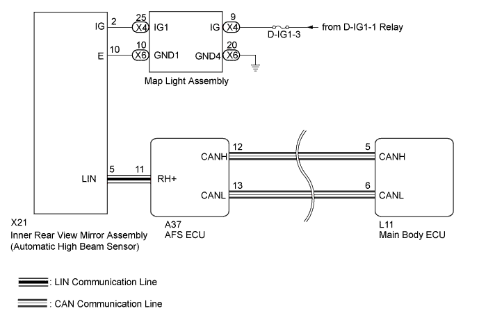
WIRING DIAGRAM
INSPECTION PROCEDURE
Note
-
First perform the communication function inspections in How to Proceed with Troubleshooting to confirm that there are no CAN communication malfunctions before troubleshooting this symptom.
-
Inspect the fuses for circuits related to this system before performing the following inspection procedure.
PROCEDURE
-
CHECK FOR DTC
-
Clear the DTC Click here.
-
Check for DTC Click here.
OK DTC B124D is not output
NG 
CHECK HARNESS AND CONNECTOR (INNER REAR VIEW MIRROR [AUTOMATIC HIGH BEAM SENSOR] - BATTERY) Click here
OK 
USE SIMULATION METHOD TO CHECK Click here
-
-
CHECK HARNESS AND CONNECTOR (INNER REAR VIEW MIRROR [AUTOMATIC HIGH BEAM SENSOR] - BATTERY)
-
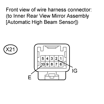
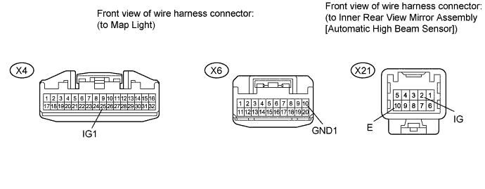
Disconnect the X21 inner rear view mirror (automatic high beam sensor) connector.
-
Measure the voltage according to the value(s) in the table below.
Standard Voltage Tester Connection Switch Condition Specified Condition X21-2 (IG) - X21-10 (E) Power switch on (IG) 11 to 14 V
NG
CHECK HARNESS AND CONNECTOR (MAP LIGHT - BATTERY AND BODY GROUND) Click here
OK 
-
-
CHECK HARNESS AND CONNECTOR (AFS ECU - INNER REAR VIEW MIRROR [AUTOMATIC HIGH BEAM SENSOR])
-
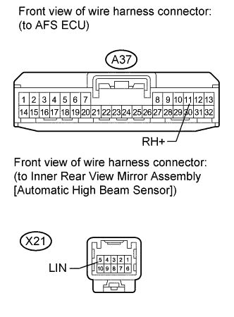
Disconnect the A37 AFS ECU connector.
-
Disconnect the X21 inner rear view mirror (automatic high beam sensor) connector.
-
Measure the resistance according to the value(s) in the table below.
Standard Resistance Tester Connection Condition Specified Condition A37-11 (RH+) - X21-5 (LIN) Always Below 1 Ω A37-11 (RH+) - Body ground Always 10 kΩ or higher
NG 
REPAIR OR REPLACE HARNESS OR CONNECTOR
OK
-
-
CHECK INNER REAR VIEW MIRROR ASSEMBLY (AUTOMATIC HIGH BEAM SENSOR)
-
Temporarily replace the inner rear view mirror (automatic high beam sensor) with a new or normally functioning one Click here.
-
Check for DTC Click here.
OK DTC B124D or B2432 is not output
NG
REPLACE AFS ECU Click here
OK
END (INNER REAR VIEW MIRROR [AUTOMATIC HIGH BEAM SENSOR] WAS DEFECTIVE)
-
-
CHECK HARNESS AND CONNECTOR (MAP LIGHT - BATTERY AND BODY GROUND)
-
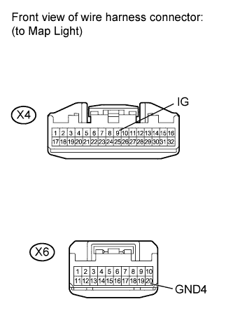
Disconnect the X4 and X6 map light connectors.
-
Measure the voltage according to the value(s) in the table below.
Standard Voltage Tester Connection Switch Condition Specified Condition X4-9 (IG) - Body ground Power switch on (IG) 11 to 14 V -
Measure the resistance according to the value(s) in the table below.
Standard Resistance Tester Connection Condition Specified Condition X6-20 (GND4) - Body ground Always Below 1 Ω
NG
REPAIR OR REPLACE HARNESS OR CONNECTOR
OK
-
-
CHECK HARNESS AND CONNECTOR (MAP LIGHT - INNER REAR VIEW MIRROR [AUTOMATIC HIGH BEAM SENSOR])
-
Disconnect the X4 and X6 map light connectors.
-
Disconnect the X21 inner rear view mirror (automatic high beam sensor) connector.
-
Measure the resistance according to the value(s) in the table below.
Standard Resistance Tester Connection Condition Specified Condition X4-25 (IG1) - X21-2 (IG) Always Below 1 Ω X6-10 (GND1) - X21-10 (E) Always Below 1 Ω X4-25 (IG1) - Body ground Always 10 kΩ or higher X6-10 (GND1) - Body ground Always 10 kΩ or higher
NG
REPAIR OR REPLACE HARNESS OR CONNECTOR
OK
REPLACE MAP LIGHT ASSEMBLY Click here
-