ENTRY AND START SYSTEM All Door Entry Lock/Unlock Functions and Wireless Functions do not Operate
DESCRIPTION
When the entry operation and wireless operation door lock function does not operate, a malfunction or wave interference may be occurring in either of the following: 1) the signal communication line between the door control receiver and certification ECU (line is used by entry and wireless); or 2) the door control transmitter.
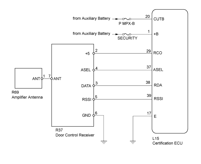
WIRING DIAGRAM
INSPECTION PROCEDURE
Note
-
Before performing the inspection, check that there are no problems related to the "CAN COMMUNICATION SYSTEM" and "LIN COMMUNICATION SYSTEM".
-
Check that there are no door control transmitters in the vehicle.
-
Before performing the inspection. check that DTC B1242 is not output Click here.
PROCEDURE
-
CHECK POWER DOOR LOCK SYSTEM
-
When the master switch's door control switch is operated, check that the locked doors unlock Click here.
OK Locked doors unlock.
NG 
GO TO POWER DOOR LOCK CONTROL SYSTEM Click here
OK 
-
-
CHECK DOOR CONTROL TRANSMITTER
-
When another registered door control transmitter is used, check that the wireless and entry function operates normally.
Result Result Proceed to Entry function operates and door control transmitter that did not operate is electrical key transmitter A Entry function operates and door control transmitter that did not operate is card key B Entry function does not operate C
B 
INSPECT TRANSMITTER BATTERY (VOLTAGE) Click here
C
CHECK WAVE ENVIRONMENT Click here
A
-
-
CHECK ELECTRICAL KEY TRANSMITTER (LED)
-
Check that the transmitter's LED illuminates 3 times when the switch is pressed 3 times.
Result Result Proceed to Transmitter's LED does not illuminate 3 times when switch is pressed 3 times A Transmitter's LED illuminates 3 times when switch is pressed 3 times B The transmitter's LED does not illuminate the second or third time C Tech Tips
If the transmitter's LED does not illuminate the second or third time, replace the transmitter battery as it is depleted.
B
REPLACE ELECTRICAL KEY TRANSMITTER
C
REPLACE TRANSMITTER BATTERY Click here
A
-
-
INSPECT TRANSMITTER BATTERY (VOLTAGE)
-
Remove the battery from the transmitter Click here.
-
Inspect the battery capacity Click here.
NG
REPLACE TRANSMITTER BATTERY Click here
OK 
REPLACE DOOR CONTROL TRANSMITTER
-
-
CHECK WAVE ENVIRONMENT
-
Bring the door control transmitter near the door control receiver, and perform a wireless and entry operation check.
Tech Tips
-
When the door control transmitter is brought near the door control receiver, the possibility of wave interference decreases, and it can be determined if wave interference is causing the problem symptom.
-
If the inspection result is that the problem only occurs in certain locations or times of day, the possibility of wave interference is high. Also, added vehicle components may cause wave interference. If installed, remove them and perform the operation check.
OK Wireless and entry functions operate normally. -
NG
INSPECT FUSE (P MPX-B, SECURITY) Click here
OK
AFFECTED BY WAVE INTERFERENCE
-
-
INSPECT FUSE (P MPX-B, SECURITY)
-
Remove the P MPX-B fuse from the passenger side junction block.
-
Remove the SECURITY fuse from the main body ECU (Driver side junction block).
-
Measure the resistance according to the value(s) in the table below.
Standard resistance Tester Connection Condition Specified Condition P MPX-B fuse Always Below 1 Ω SECURITY fuse Always Below 1 Ω
NG
REPLACE FUSE
OK
-
-
CHECK HARNESS AND CONNECTOR (CERTIFICATION ECU - BATTERY)
-
Disconnect the L15 ECU connector.
-
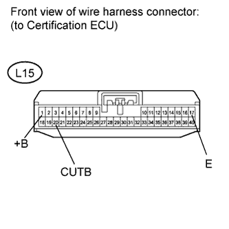
Measure the resistance and voltage according to the value(s) in the table below.
Standard resistance Tester Connection Condition Specified Condition L15-17 (E) - Body ground Always Below 1 Ω Standard voltage Tester Connection Condition Specified Condition L15-20 (CUTB) - Body ground Always 11 to 14 V L15-1 (+B) - Body ground Always 11 to 14 V
NG
REPAIR OR REPLACE HARNESS OR CONNECTOR
OK
-
-
CHECK HARNESS AND CONNECTOR (CERTIFICATION ECU - DOOR CONTROL RECEIVER AND BODY GROUND)
-
Disconnect the R37 receiver connector.
-
Disconnect the L15 ECU connector.
-
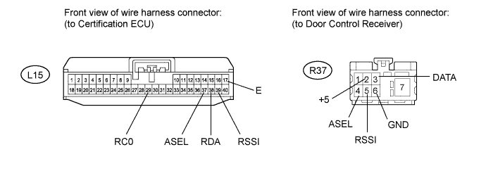
Measure the resistance according to the value(s) in the table below.
Standard resistance Tester Connection Condition Specified Condition L15-29 (RCO) - R37-2 (+5) Always Below 1 Ω L15-38 (RDA) - R37-3 (DATA) Always Below 1 Ω L15-37 (ASEL) - R37-4 (ASEL) Always Below 1 Ω L15-39 (RSSI) - R37-5 (RSSI) Always Below 1 Ω L15-17(E) - Body ground Always Below 1 Ω R37-6 (GND) - Body ground Always Below 1 Ω L15-29 (RCO) or R37-2 (+5) - Body ground Always 10 kΩ or higher L15-38 (RDA) or R37-3 (DATA) - Body ground Always 10 kΩ or higher L15-37 (ASEL) or R37-4 (ASEL) - Body ground Always 10 kΩ or higher L15-39 (RSSI) or R37-5 (RSSI) - Body ground Always 10 kΩ or higher
NG
REPAIR OR REPLACE HARNESS OR CONNECTOR
OK
-
-
CHECK BACK WINDOW GLASS (WINDOW GLASS ANTENNA WIRE)
-
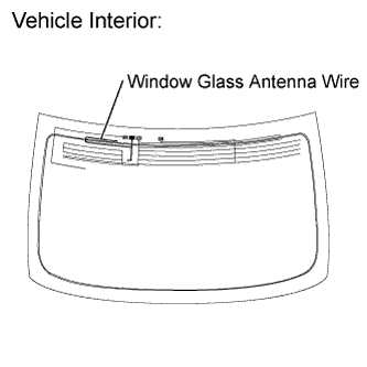
Visually inspect the entire window glass antenna wire's lines for breaks.
-
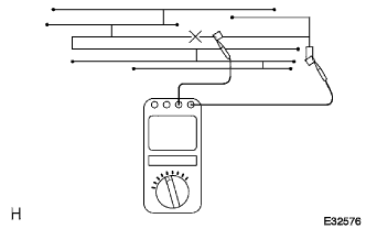
Using the tester, check that the window glass antenna wire's lines do not have continuity breaks.
Note
-
-
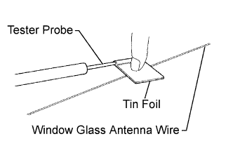
Wrap a piece of tin foil around the tip of the negative (-) tester probe as shown in the illustration. Press the foil against the wire's lines with your finger without damaging the wire, and inspect the wire.
-
If foreign matter on the glass needs to be cleaned, use a soft, dry cloth to wipe the glass along the wire's lines without damaging the wire.
-
Do not use standard detergents or glass cleaners.
-
Move the tin foil wrapped probe along the wire's lines, and check for line breaks.
OK Based on visual inspection and tester inspection, wire line breaks are not present.
-
NG
REPAIR WINDOW GLASS ANTENNA WIRE Click here
OK
-
-
CHECK HARNESS AND CONNECTOR (DOOR CONTROL RECEIVER - AMPLIFIER ANTENNA)
-
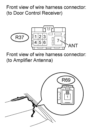
Disconnect the R37 receiver connector.
-
Disconnect the R69 antenna connector.
-
Measure the resistance according to the value(s) in the table below.
Standard resistance Tester Connection Condition Specified Condition R37-7 (ANT) - R69-1 (ANT) Always Below 1 Ω R37-7 (ANT) or R69-1 (ANT) - Body ground Always 10 kΩ or higher
NG
REPAIR OR REPLACE HARNESS OR CONNECTOR
OK
-
-
CHECK AMPLIFIER ANTENNA ASSEMBLY (OPERATION)
-
Temporarily replace the amplifier antenna with a new one Click here.
-
Check that the wireless and entry functions operate normally.
OK Wireless and entry functions operate normally.
NG
CHECK DOOR CONTROL RECEIVER (OPERATION) Click here
OK
END (AMPLIFIER ANTENNA IS DEFECTIVE)
-
-
CHECK DOOR CONTROL RECEIVER (OPERATION)
-
Temporarily replace the door control receiver with a new one Click here.
-
Check that the wireless and entry functions operate normally.
OK Wireless and entry functions operate normally
NG
REPLACE CERTIFICATION ECU
OK
END (DOOR CONTROL RECEIVER IS DEFECTIVE)
-