ENGINE ASSEMBLY REMOVAL

CAUTION:
As the engine assembly with transmission is extremely heavy, the engine lifter may suddenly drop if the instructions listed in the repair manual are not followed. Therefore, always follow the instructions listed in the repair manual when performing this procedure.
-
PLACE FRONT WHEELS FACING STRAIGHT AHEAD
-
RECOVER REFRIGERANT FROM REFRIGERATION SYSTEM
-
Turn the power switch on (READY).
-
Turn the A/C switch on.
-
Operate the air conditioning with a set temperature of 25°C (77°F) and the blower at low for 10 minutes to circulate the refrigerant. This causes most of the compressor oil from the various components of the air conditioning system to collect in the air conditioning compressor.
-
Turn the power switch off.
-
Recover the refrigerant from the air conditioning system using a refrigerant recovery unit.
-
-
DISCHARGE FUEL SYSTEM PRESSURE
-
REMOVE LUGGAGE COMPARTMENT MAT SUB-ASSEMBLY (w/ Spare Tire)

-
REMOVE DECK BOARD ASSEMBLY (w/o Spare Tire)

-
REMOVE DECK TRIM SIDE BOARD LH (w/o Spare Tire)
-

Detach the 2 clips and remove the deck trim side board LH.
-
-
REMOVE BATTERY SERVICE HOLE COVER LH
-

Text in Illustration *A for Standard *B for Ottoman *1 Fastening Tape Detach the clip, fastening tape and remove the battery service hole cover LH.
-
-
PRECAUTION
Note
After turning the power switch off, waiting time may be required before disconnecting the cable from the auxiliary battery terminal. Therefore, make sure to read the disconnecting the cable from the auxiliary battery terminal notice before proceeding with work Click here.
-
DISCONNECT CABLE FROM AUXILIARY BATTERY NEGATIVE TERMINAL
CAUTION:
Wait at least 90 seconds after disconnecting the cable from the auxiliary negative (-) battery terminal to prevent airbag and seat belt pretensioner activation.
Note
When disconnecting the cable, some systems need to be initialized after the cable is reconnected Click here.
-
REMOVE SERVICE PLUG GRIP
-
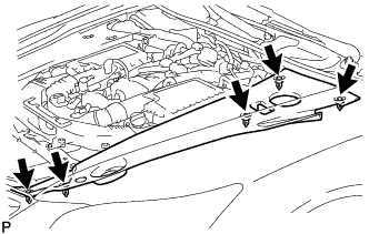
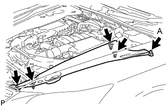
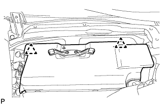
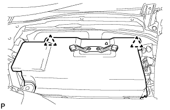
REMOVE V-BANK COVER SUB-ASSEMBLY
-

While using both hands, lift the rear side of the V-bank cover sub-assembly upwards to detach the 4 clips labeled B. Slide the V-bank cover sub-assembly towards the front of the vehicle to detach the 2 clips labeled A, and remove the V-bank cover sub-assembly.
Note
The V-bank cover sub-assembly may be damaged if its front and rear are lifted at the same time.
-
-
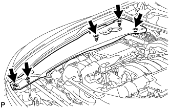
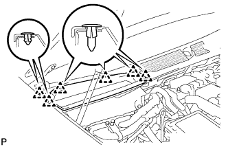
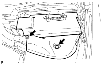
REMOVE AIR CLEANER INLET COVER SUB-ASSEMBLY
-
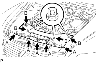
Remove the 5 clips labeled A.
-
Lift up the air cleaner inlet cover sub-assembly to detach the 4 clips labeled B, and remove the air cleaner inlet cover sub-assembly.
-
-
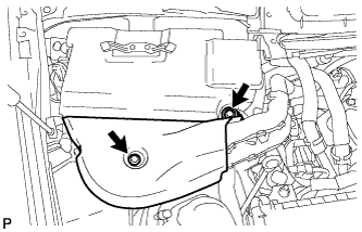
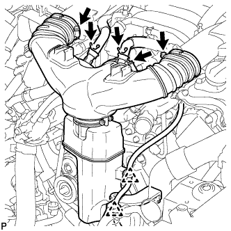
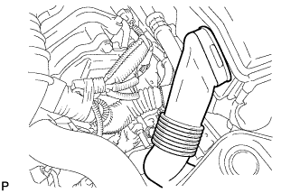
REMOVE NO. 1 AIR CLEANER INLET
-
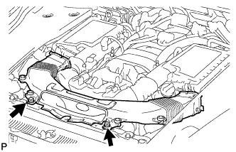
Remove the 2 bolts.
-
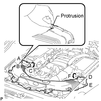
Hold the No. 1 air cleaner inlet by the protrusions labeled A and B, and detach the connections.
-
Rotate the No. 1 air cleaner inlet as shown in the illustration to detach the protrusion labeled C.
-
Hold the No. 1 air cleaner inlet by the protrusions labeled D and E, and detach the connections.
-
Rotate the No. 1 air cleaner inlet as shown in the illustration to detach the protrusion labeled F.
-
-
REMOVE ENGINE ROOM SIDE COVER RH
-
for LHD:
Remove the 5 clips and engine room side cover RH.
Note
Remove the clip labeled A by turning it to prevent the engine room side cover RH and bracket from being damaged.
Tech Tips
The clip labeled A cannot be removed from the engine room side cover RH.
-
for RHD:
Remove the 5 clips and engine room side cover RH.
-
-
REMOVE ENGINE ROOM SIDE COVER LH
-
for LHD:
Remove the 5 clips and engine room side cover LH.
-
for RHD:
Remove the 5 clips and engine room side cover LH.
Note
Remove the clip labeled A by turning it to prevent the engine room side cover LH and bracket from being damaged.
Tech Tips
The clip labeled A cannot be removed from the engine room side cover LH.
-
-
REMOVE COWL TOP VENTILATOR LOUVER RH (for LHD)
-
Remove the 6 clips and cowl top ventilator louver RH.
-
-
REMOVE COWL TOP VENTILATOR LOUVER LH (for RHD)
Tech Tips
Use the same procedures described for LHD vehicles.
-
REMOVE MOTOR CABLE COVER RH (for LHD)
-
Remove the 2 clips and motor cable cover RH.
-
-
REMOVE MOTOR CABLE COVER LH (for RHD)
-
Remove the 2 clips and motor cable cover LH.
-
-
REMOVE INVERTER COVER ASSEMBLY RH (for LHD)
-
Detach the 2 clips and remove the inverter cover assembly RH.
-
-
REMOVE INVERTER COVER ASSEMBLY LH (for RHD)
-
Detach the 2 clips and remove the inverter cover assembly LH.
-
-
REMOVE CONNECTOR COVER ASSEMBLY (for LHD)
CAUTION:
Wear insulating gloves.
-
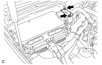
Using an insulated tool, remove the 2 bolts and connector cover assembly.
Note
-
Cover the hole where the cable was connected with tape or equivalent (non-residue type) to prevent entry of foreign matter.
-
Do not touch the high voltage connectors or terminals for 10 minutes after the service plug grip is removed.
-
-
-
CHECK TERMINAL VOLTAGE (for LHD)
CAUTION:
Wear insulating gloves.
-
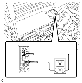
Using the voltmeter, measure the voltage between the terminals of the 2 phase connectors.
Standard voltage 0 V Tech Tips
Use measuring range of DC 750 V or more on the voltmeter.
-
-
INSTALL CONNECTOR COVER ASSEMBLY (for LHD)
CAUTION:
Wear insulating gloves.
-
Using an insulated tool, install the connector cover assembly with the 2 bolts.
- Torque:
- 8.0 N*m { 82 kgf*cm, 71 in.*lbf }
-
-
REMOVE CONNECTOR COVER ASSEMBLY (for RHD)
CAUTION:
Wear insulating gloves.
-
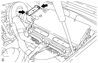
Using an insulated tool, remove the 2 bolts and connector cover assembly.
Note
-
Cover the hole where the cable was connected with tape or equivalent (non-residue type) to prevent entry of foreign matter.
-
Do not touch the high voltage connectors or terminals for 10 minutes after the service plug grip is removed.
-
-
-
CHECK TERMINAL VOLTAGE (for RHD)
CAUTION:
Wear insulating gloves.
-
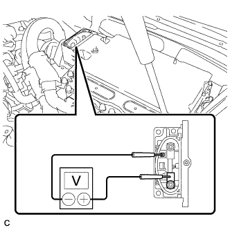
Using the voltmeter, measure the voltage between the terminals of the 2 phase connectors.
Standard voltage 0 V Tech Tips
Use measuring range of DC 750 V or more on the voltmeter.
-
-
INSTALL CONNECTOR COVER ASSEMBLY (for RHD)
CAUTION:
Wear insulating gloves.
-
Using an insulated tool, install the connector cover assembly with the 2 bolts.
- Torque:
- 8.0 N*m { 82 kgf*cm, 71 in.*lbf }
-
-
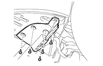
REMOVE FRONT CENTER FLOOR COVER (w/ Cover)
-
Remove the 3 screws, 2 bolts, clip and front center floor cover.
-
-
REMOVE NO. 2 ENGINE UNDER COVER
-
Remove the 4 screws, 2 clips and No. 2 engine under cover.
-
-
REMOVE FRONT WHEEL OPENING EXTENSION PAD RH
-
Remove the 5 screws and front wheel opening extension pad LH.
-
-
REMOVE FRONT WHEEL OPENING EXTENSION PAD LH
Tech Tips
Use the same procedure described for the LH side.
-
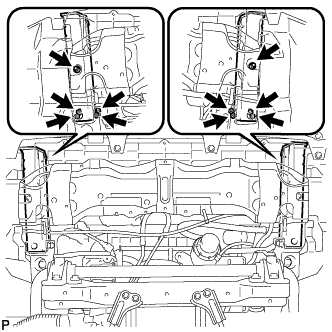
REMOVE NO. 1 ENGINE UNDER COVER
-
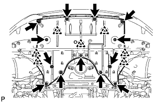
Remove the 13 screws, 7 clips and No. 1 engine under cover.
-
-
REMOVE FRONT LOWER SUSPENSION MEMBER PROTECTOR
-
Remove the 9 bolts and front lower suspension member protector.
-
-
DRAIN ENGINE OIL
-
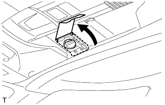
Open the oil filler cap service hole cover.
-
Remove the oil filler cap.
-
Remove the oil pan drain plug and gasket, and drain the engine oil into a container.
-
Install a new gasket and the oil pan drain plug.
- Torque:
- 40 N*m { 408 kgf*cm, 30 ft.*lbf }
-
-
DRAIN ENGINE COOLANT
CAUTION:
Do not remove the radiator reservoir cap and vent plug while the engine and radiator are still hot. Pressurized, hot engine coolant and steam may be released and cause serious burns.
-
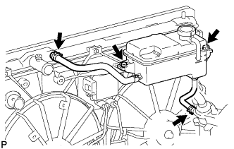
Loosen the radiator drain cock plug.
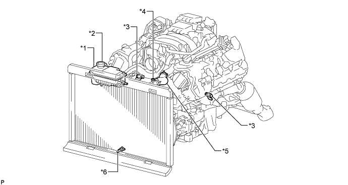
Text in Illustration *1 Radiator Reservoir *2 Radiator Reservoir Cap *3 Cylinder Block Drain Cock Plug *4 Vent Plug *5 No. 1 Radiator Hose *6 Radiator Drain Cock Plug Tech Tips
Collect the coolant in a container and dispose of it according to the regulations in your area.
-
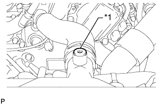
Text in Illustration *1 Vent Plug Remove the radiator reservoir cap, and using a 6 mm hexagon wrench, remove the vent plug.
-
Drain the coolant.
-
Loosen the 2 cylinder block drain cock plugs.
-
-
DRAIN COOLANT (for Inverter)
Note
-
Do not reuse the drained coolant because it may contain foreign objects.
-
Collect the drained coolant and measure its volume to establish a benchmark. When adding coolant, make sure to add more coolant than the measured amount.
-
Remove the inverter reserve tank cap.
CAUTION:
To avoid the danger of being burned, do not remove the inverter reserve tank cap while the coolant for the inverter is still hot.
Note
Do not remove the plug from the tube.
-
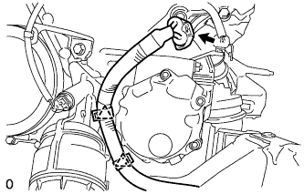
Using a hexagon wrench 10 mm, remove the drain plug indicated in the illustration and drain the coolant.
CAUTION:
Use caution when handling coolant immediately after driving or in summer because it may be hot.
-
Using a hexagon wrench 10 mm, install the drain plug with a new gasket.
- Torque:
- 39 N*m { 400 kgf*cm, 29 ft.*lbf }
-
Measure the volume of the drained coolant.
-
-
DRAIN FRONT DIFFERENTIAL OIL
-
Stop the vehicle on a level place.
-
for Front Differential:
-
Using a 10 mm hexagon wrench, remove the filler plug and gasket.
-
Using a 10 mm hexagon wrench, remove the drain plug and gasket, and drain the oil.
-
Using a 10 mm hexagon wrench, install a new gasket and the drain plug.
- Torque:
- 39 N*m { 398 kgf*cm, 29 ft.*lbf }
-
-
for Rear Differential:
-
Using a 10 mm hexagon wrench, remove the filler plug and gasket.
-
Using a 10 mm hexagon wrench, remove the drain plug and gasket, and drain the oil.
-
Using a 10 mm hexagon wrench, install a new gasket and the drain plug.
- Torque:
- 49 N*m { 500 kgf*cm, 37 ft.*lbf }
-
-
-
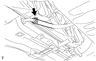
DISCONNECT INLET OIL COOLER HOSE
-
Disconnect the No. 2 oil cooler inlet hose from the radiator assembly.
Note
Place a container under the connection before disconnecting the oil cooler hose because oil in the hose may spill out.
-
-
DISCONNECT OUTLET OIL COOLER HOSE
-
Disconnect the No. 2 oil cooler outlet hose from the radiator assembly.
Note
Place a container under the connection before disconnecting the oil cooler hose because oil in the hose may spill out.
-
-
REMOVE FRONT BUMPER COVER
-
DISCONNECT FRONT FENDER LINER LH (w/ Active Stabilizer System)
-
Remove the 3 screws.
-
Partially remove the fender liner.
Tech Tips
It is not necessary to fully remove the fender liner. Partially remove it so that the ECU can be removed.
-
-
REMOVE NO. 3 COOL AIR INTAKE DUCT SUB-ASSEMBLY (w/ Active Stabilizer System)
-
Detach the clamp, remove the 2 bolts.
-
Detach the 2 claws and remove the duct.
-
-
REMOVE INLET ENGINE ROOM ECM DUCT (w/ Active Stabilizer System)
-
Remove the duct from the ECM box.
-
-
DISCONNECT FRONT ACTIVE STABILIZER CONTROL ACTUATOR CONNECTOR (w/ Active Stabilizer System)
-
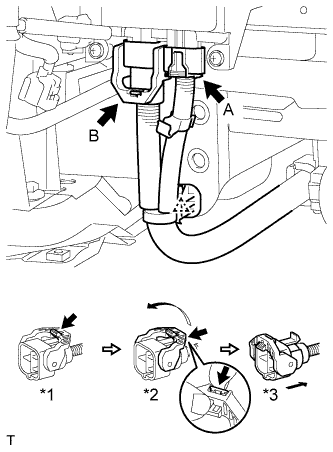
Disconnect the wire harness clamp.
-
Disconnect the actuator connector labeled A.
-
Disconnect the actuator connector labeled B.
-
Release the lever's lock. (*1)
-
Press the claw and move the lever in the direction of the arrow in the illustration. (*2)
-
Disconnect the actuator connector. (*3)
Note
When disconnecting the actuator connector, do not apply excessive force to the wire harness.
-
-
-
REMOVE REAR FRAME SIDE RAIL
-
Remove the 6 bolts, 4 nuts and 2 rear frame side rails.
-
-
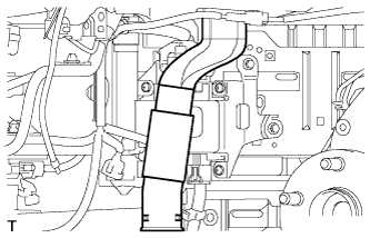
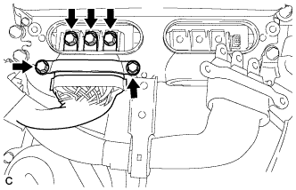
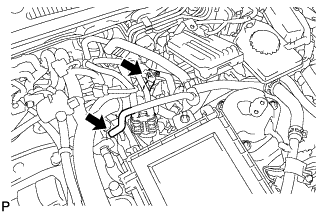
REMOVE INTAKE AIR CONNECTOR PIPE
-
Disconnect the No. 1 ventilation hose and No. 2 ventilation hose from the intake air connector pipe.
-
Using a clip remover, detach the 2 wire harness clamps.
-
Loosen the 3 hose clamps, and remove the intake air connector pipe.
-
-
REMOVE AIR CLEANER ASSEMBLY LH
-
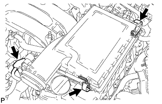
Disconnect the mass air flow meter connector.
-
Release the 2 clamps and remove the air cleaner cap LH.
-
Remove the air cleaner filter element from the air cleaner case LH.
-
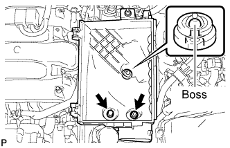
Remove the 2 nuts and detach the air cleaner case LH from the boss.
-
-
REMOVE AIR CLEANER ASSEMBLY RH
-
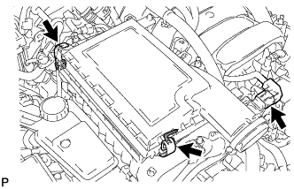
Disconnect the mass air flow meter connector.
-
Release the 2 clamps and remove the air cleaner cap RH.
-
Remove the air cleaner filter element from the air cleaner case RH.
-
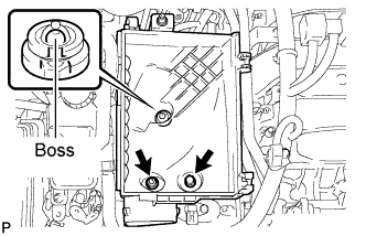
Remove the 2 nuts and detach the air cleaner case RH from the boss.
-
-
REMOVE RADIATOR RESERVOIR ASSEMBLY
-
Disconnect the 2 reservoir hoses.
-
Remove the 2 bolts and radiator reservoir assembly.
-
-
REMOVE OUTLET ENGINE ROOM ECM DUCT
-
Remove the outlet engine room ECM duct.
-
-
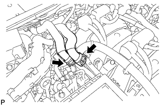
REMOVE NO. 1 RADIATOR HOSE
-
REMOVE NO. 2 RADIATOR HOSE
-
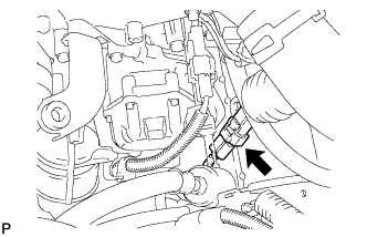
REMOVE RESONATOR BRACKET SUB-ASSEMBLY
-

Remove the bolt and resonator bracket sub-assembly.
-
-
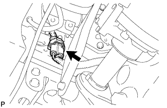
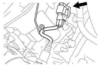
REMOVE ENGINE OIL PRESSURE SWITCH ASSEMBLY
-
Disconnect the switch connector.
-
Using a 24 mm deep socket wrench, remove the switch.
-
-
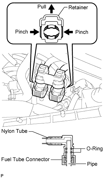
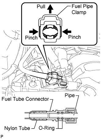
DISCONNECT NO. 1 FUEL HOSE
-
Lift up the retainer to release its lock.
-
Pinch the tube connector and then pull out the fuel pipe.
Note
-
Check for any dirt and foreign matter contamination in the pipe and around the connector. Clean if necessary. Foreign matter may damage the O-rings or cause leaks in the seal between the pipe and connector.
-
Do not use any tools to separate the pipe and connector.
-
Do not forcefully bend or twist the nylon tube.
-
Check for any dirt and foreign matter on the pipe seal surface. Clean if necessary.
-
Put the pipe and connector ends in plastic bags to prevent damage and dirt contamination.
-
If the pipe and connector are stuck together, pinch the tube between your fingers and turn it carefully to free it. Then disconnect the pipe.
-
-
-
DISCONNECT NO. 3 FUEL HOSE
-
Remove the fuel pipe clamp.
-
Pinch the tube connector and then pull out the fuel hose.
Note
-
Check for any dirt and foreign matter contamination in the pipe and around the connector. Clean if necessary. Foreign matter may damage the O-rings or cause leaks in the seal between the pipe and connector.
-
Do not use any tools to separate the pipe and connector.
-
Do not forcefully bend or twist the nylon tube.
-
Check for any dirt and foreign matter on the pipe seal surface. Clean if necessary.
-
Put the pipe and connector ends in plastic bags to prevent damage and dirt contamination.
-
If the pipe and connector are stuck together, pinch the tube between your fingers and turn it carefully to free it. Then disconnect the hose.
-
-
-
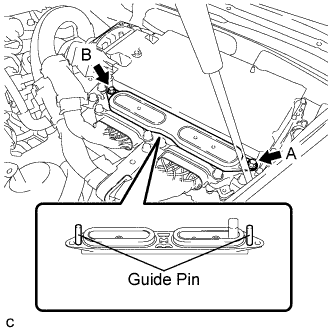
REMOVE INVERTER TERMINAL COVER (for LHD)
CAUTION:
Wear insulating gloves.
Note
Lift the inverter terminal cover horizontally so that it will not tilt. Failure to do so may break the inverter cover guide pins.
-
Using an insulated tool, remove the 2 bolts.
-
Insert and gradually rotate a screwdriver between the inverter terminal cover and inverter case near bolt hole A to raise the terminal cover by approximately 2 mm (0.08 in.). (*1)
Note
Tape the screwdriver tip before use.
-
Insert and gradually rotate a screwdriver between the inverter terminal cover and inverter case near bolt hole B to raise the terminal cover by approximately 2 mm (0.08 in.). (*2)
Note
Tape the screwdriver tip before use.
Tech Tips
Repeat the preceding steps (*1) and (*2) until the inverter cover can be easily removed by hand.
-
Remove the inverter terminal cover by hand.
Note
-
Do not allow any foreign objects to enter the waterproofed parts of the removed inverter terminal cover.
-
Do not touch the waterproofed parts.
-
When removing the inverter terminal cover, do not bend the connector terminals around the interlock part.
-
Cover the hole where the cable was connected with tape or equivalent (non-residue type) to prevent entry of foreign matter.
-
-
-
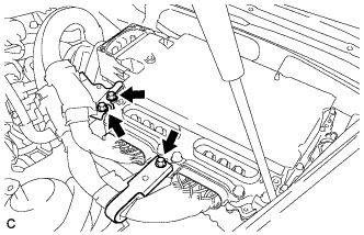
DISCONNECT MOTOR CABLE (for LHD)
CAUTION:
Wear insulating gloves.
-
Remove the 3 bolts and separate the motor cable bracket.
-
Using an insulated tool, remove the 5 bolts and pull out the motor cable from the inverter with converter assembly.
Note
-
Cover the hole where the cable was connected with tape or equivalent (non-residue type) to prevent entry of foreign matter.
-
When removing the bolts that secure the cable, do not damage anything inside the inverter with converter assembly.
-
-
-
DISCONNECT GENERATOR CABLE (for LHD)
CAUTION:
Wear insulating gloves.
-
Using an insulated tool, remove the 5 bolts and pull out the generator cable from the inverter with converter assembly.
Note
-
Cover the hole where the cable was connected with tape or equivalent (non-residue type) to prevent entry of foreign matter.
-
When removing the bolts that secure the cable, do not damage anything inside the inverter with converter assembly.
-
-
-
REMOVE INVERTER TERMINAL COVER (for RHD)
CAUTION:
Wear insulating gloves.
Note
Lift the inverter terminal cover horizontally so that it will not tilt. Failure to do so may break the inverter cover guide pins.
-
Using an insulated tool, remove the 2 bolts.
-
Insert and gradually rotate a screwdriver between the inverter terminal cover and inverter case near bolt hole A to raise the terminal cover by approximately 2 mm (0.08 in.). (*1)
Note
Tape the screwdriver tip before use.
-
Insert and gradually rotate a screwdriver between the inverter terminal cover and inverter case near bolt hole B to raise the terminal cover by approximately 2 mm (0.08 in.). (*2)
Note
Tape the screwdriver tip before use.
Tech Tips
Repeat the preceding steps (*1) and (*2) until the inverter cover can be easily removed by hand.
-
Remove the inverter terminal cover by hand.
Note
-
Do not allow any foreign objects to enter the waterproofed parts of the removed inverter terminal cover.
-
Do not touch the waterproofed parts.
-
When removing the inverter terminal cover, do not bend the connector terminals around the interlock part.
-
Cover the hole where the cable was connected with tape or equivalent (non-residue type) to prevent entry of foreign matter.
-
-
-
DISCONNECT MOTOR CABLE (for RHD)
CAUTION:
Wear insulating gloves.
-
Remove the 3 bolts and separate the motor cable bracket.
-
Using an insulated tool, remove the 5 bolts and pull out the motor cable from the inverter with converter assembly.
Note
-
Cover the hole where the cable was connected with tape or equivalent (non-residue type) to prevent entry of foreign matter.
-
When removing the bolts that secure the cable, do not damage anything inside the inverter with converter assembly.
-
-
-
DISCONNECT GENERATOR CABLE (for RHD)
CAUTION:
Wear insulating gloves.
-
Using an insulated tool, remove the 5 bolts and pull out the generator cable from the inverter with converter assembly.
Note
-
Cover the hole where the cable was connected with tape or equivalent (non-residue type) to prevent entry of foreign matter.
-
When removing the bolts that secure the cable, do not damage anything inside the inverter with converter assembly.
-
-
-
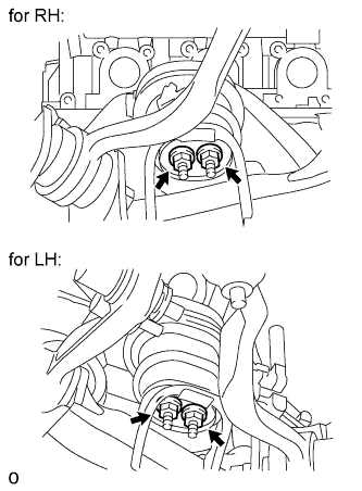
DISCONNECT DISCHARGE HOSE SUB-ASSEMBLY
-
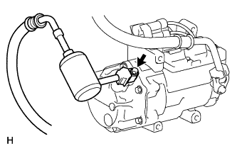
Remove the bolt. Then disconnect the discharge hose sub-assembly.
-
Remove the O-ring from the discharge hose sub-assembly.
Note
Seal the openings of the disconnected parts and motor compressor using vinyl tape and/or plastic bags to prevent moisture and foreign matter from entering them.
-
-
DISCONNECT SUCTION HOSE SUB-ASSEMBLY
-
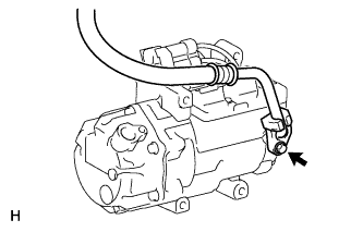
Remove the bolt. Then disconnect the suction hose sub-assembly.
-
Remove the O-ring from the suction hose sub-assembly.
Note
Seal the openings of the disconnected parts and motor compressor using vinyl tape and/or plastic bags to prevent moisture and foreign matter from entering them.
-
-
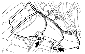
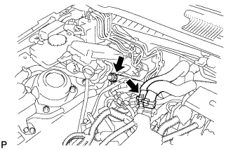
REMOVE WATER PUMP ASSEMBLY WITH MOTOR AND BRACKET
-
Disconnect the water pump connector.
Note
Wrap the connectors of the vehicle wire harness and the water pump with motor and bracket assembly to prevent coolant from contaminating the connectors.
-
Remove the 2 clips and disconnect the 2 water pump hoses.
Note
Apply insulating tape to the pipe and in the disconnected hose or cover the pipe and hose with plastic bags to prevent entry of foreign matter.
-
Remove the 2 bolts and water pump with motor and bracket assembly.
-
-
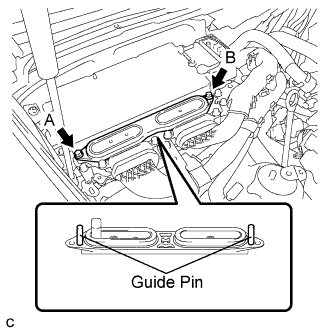
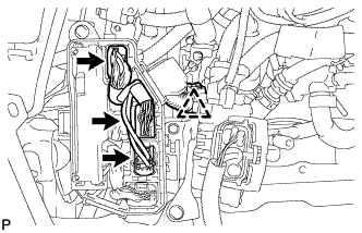
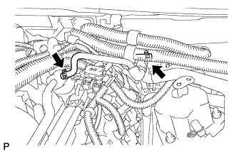
DISCONNECT HOSES AND CONNECTORS
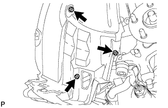
-
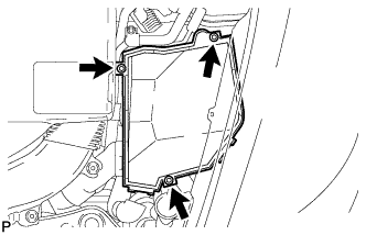
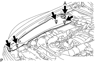
Remove the 3 bolts and engine room ECU cover.
-
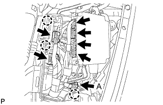
Disconnect the 4 hybrid vehicle control ECU connectors and 2 wiring harness support connectors.
-
Detach the 2 wiring harness support clips, and then detach the clip of connector A from the ECM box.
Tech Tips
It is not necessary to disconnect the connection at A in the illustration.
-
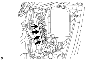
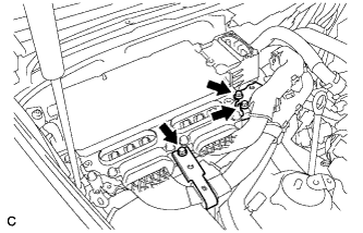
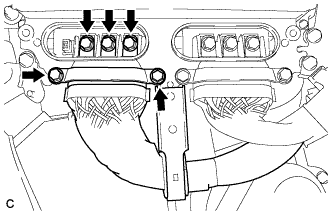
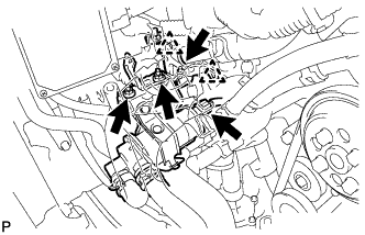
Lift up the wiring harness support and disconnect the 4 ECM connectors.
-
Detach the clamp and disconnect the 3 connectors from the front controller.
-
Remove the nut and ground wire.
-
Disconnect the 2 oil pump motor controller connectors.
Tech Tips
Refer to the following procedures to disconnect the oil pump driver connector Click here.
-
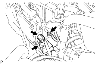
Disconnect the heater water pump connector.
-
Detach the 2 clamps. Then remove the nut and inverter cooling pipe bracket.
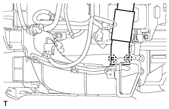
-
Remove the 2 nuts, heater water pump and bracket.
-
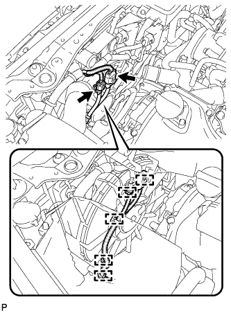
Disconnect the 2 connectors and detach the 5 clamps.
-
for LHD:
-
Disconnect the heater wire connector.
-
Disconnect the No. 5 inverter cooling hose and purge line hose.
-
Disconnect the 2 heater hoses.
-
-
for RHD:
-
Disconnect the heater wire connector.
-
Disconnect the outlet No. 2 inverter cooling hose and purge line hose.
-
Disconnect the 2 heater hoses and No. 6 inverter cooling hose.
-
-
-
REMOVE DRIVER SIDE KNEE AIRBAG ASSEMBLY
-
REMOVE NO. 1 AIR DUCT SUB-ASSEMBLY (for RHD)
-
Detach the 2 claws, and remove the bolt and No. 1 air duct sub-assembly.
Note
Be careful not to damage the No. 1 air duct sub-assembly as its connection to the vehicle is very tight.
-
-
REMOVE NO. 2 AIR DUCT SUB-ASSEMBLY (for LHD)
-
Detach the 2 claws, and remove the bolt and No. 2 air duct sub-assembly.
Note
Be careful not to damage the No. 2 air duct subassembly as its connection to the vehicle is very tight.
-
-
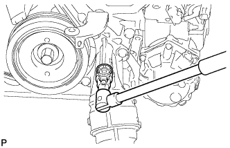
REMOVE NO. 2 STEERING INTERMEDIATE SHAFT ASSEMBLY
-
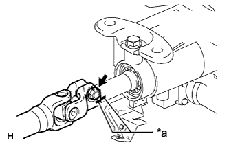
Text in Illustration *a Matchmark Put matchmarks on the No. 2 steering intermediate shaft and the steering column.
-
Remove the bolt.
-
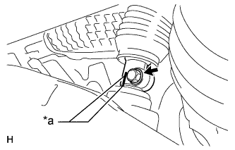
Text in Illustration *a Matchmark Put matchmarks on the No. 2 steering intermediate shaft and the steering link.
-
Remove the bolt.
-
Remove the clamp and No. 2 steering intermediate shaft.
-
-
REMOVE FRONT DRIVE SHAFT ASSEMBLY
-
REMOVE FRONT EXHAUST PIPE ASSEMBLY
-
REMOVE PROPELLER SHAFT WITH CENTER BEARING ASSEMBLY
-
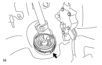
DISCONNECT TRANSMISSION CONTROL SHAFT LEVER
-
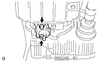
Remove the nut and spring washer, and then disconnect the transmission control shaft lever from the position sensor.
-
-
DISCONNECT FRONT LOWER SHOCK ABSORBER BRACKET SUB-ASSEMBLY RH
-
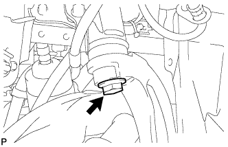
Remove the bolt. Then disconnect the front lower shock absorber bracket sub-assembly RH.
-
-
DISCONNECT FRONT LOWER SHOCK ABSORBER BRACKET SUB-ASSEMBLY LH
-
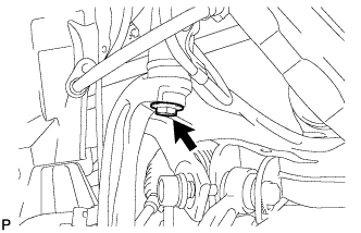
Remove the bolt. Then disconnect the front lower shock absorber bracket sub-assembly LH.
-
-
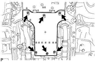
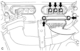
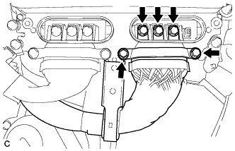
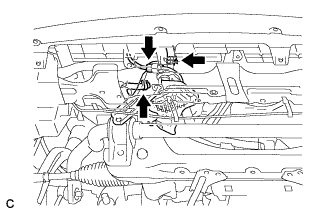
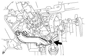
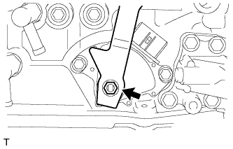
REMOVE ENGINE AND TRANSMISSION
-
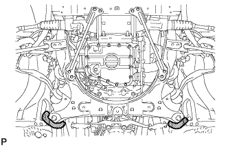
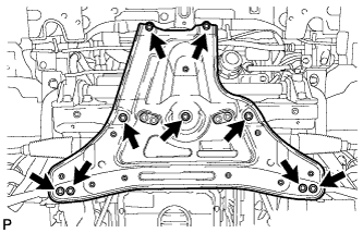
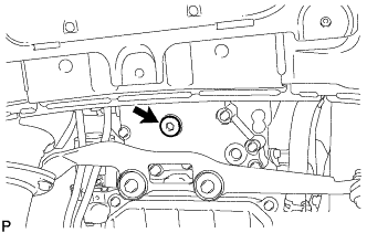
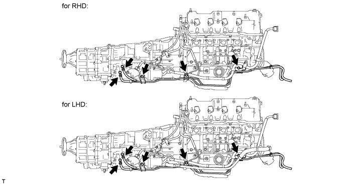
Place a mark (with spray, etc.) over the rear right vehicle side attachment area of the front frame, which is indicated in the illustration.
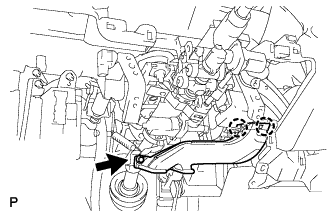
-
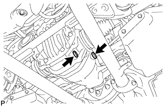
Place a mark (with spray, etc.) over the rear left vehicle side attachment area of the front frame.
-
Set an engine lifter underneath the engine.
Note
-
Place wooden blocks or plate lift attachments so that the engine is level.
-
With the exception of installing the engine assembly to an engine stand or removing the engine assembly from an engine stand, do not perform any work on the engine while it is suspended, as doing so is dangerous.
-
Never install attachments to the oil pan of the engine assembly or transmission as doing so may deform the oil pan.
-
-
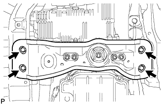
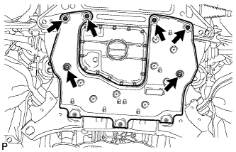
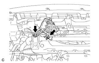
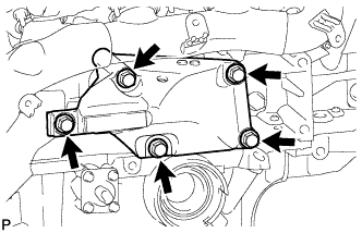
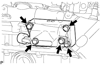
Remove the 4 rear engine mounting member's bolts.
-
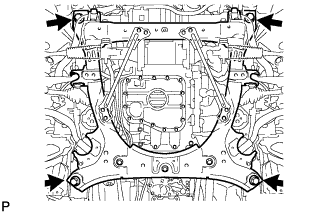
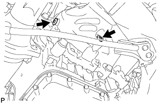
Remove the 4 bolts shown in the illustration.
-
Operate the engine lifter, then slowly remove the engine from the vehicle.
Note
-
Make sure that the engine is clear of all wiring and hoses.
-
While lowering the engine from the vehicle, do not allow it to contact the vehicle.
-
-
-
INSTALL ENGINE HANGER
-
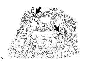
Install the 2 engine hangers with the 2 bolts as shown in the illustration.
- Torque:
- 43 N*m { 438 kgf*cm, 32 ft.*lbf }
Tech Tips
Engine hanger 12281-38150 Bolt 90119-14120 -
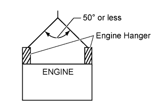
Attach an engine sling device and hang the engine with a chain block.
Note
When hanging the engine, make sure to hang the engine with the sling device's hanging angle at 50° or less. If not, the engine or engine hangers may be damaged.
-
-
REMOVE FRONT FRAME ASSEMBLY
-
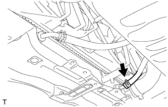
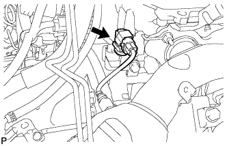
Disconnect the heater wire connector and detach the 2 clips.
-
Remove the 4 nuts and front frame assembly.
-
-
REMOVE ENGINE OIL LEVEL DIPSTICK GUIDE
-
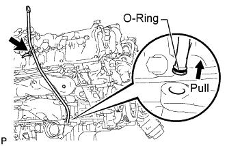
Remove the engine oil level dipstick.
-
Remove the bolt and engine oil level dipstick guide.
-
Remove the O-ring from the engine oil level dipstick guide.
-
-
REMOVE NO. 1 EXHAUST MANIFOLD HEAT INSULATOR
-
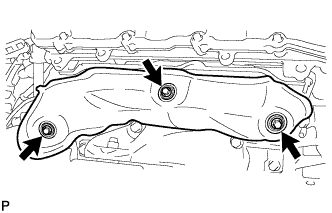
Remove the 3 bolts and heat insulator.
-
-
REMOVE NO. 2 EXHAUST MANIFOLD HEAT INSULATOR
-
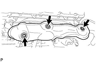
Remove the 3 bolts and heat insulator.
-
-
REMOVE FRONT ENGINE MOUNTING INSULATOR
-
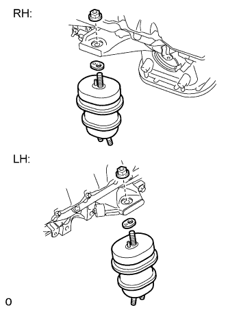
Remove the 2 nuts, 2 spacers and 2 front engine mounting insulators.
-
-
REMOVE FRONT NO. 1 ENGINE MOUNTING BRACKET RH
-
Remove the 5 bolts and front No. 1 engine mounting bracket RH.
-
-
REMOVE FRONT NO. 1 ENGINE MOUNTING BRACKET LH
-
Remove the 5 bolts and front No. 1 engine mounting bracket LH.
-
-
REMOVE EXHAUST MANIFOLD SUB-ASSEMBLY RH
-
Disconnect the air fuel ratio sensor connector.
-
Remove the 8 nuts and exhaust manifold RH.
-
Remove the gasket.
-
-
REMOVE EXHAUST MANIFOLD SUB-ASSEMBLY LH
-
Disconnect the air fuel ratio sensor connector.
-
Remove the 8 nuts and exhaust manifold LH.
-
Remove the gasket.
-
-
REMOVE FRONT NO. 2 ENGINE MOUNTING BRACKET RH
-
Remove the 2 bolts and front No. 2 engine mounting bracket RH.
-
-
REMOVE FRONT NO. 2 ENGINE MOUNTING BRACKET LH
-
Remove the 2 bolts and front No. 2 engine mounting bracket LH.
-
-
REMOVE FRONT PROPELLER SHAFT ASSEMBLY
-
REMOVE REAR ENGINE MOUNTING MEMBER
Tech Tips
Only perform this procedure when replacement of the rear engine mounting member is necessary.
-
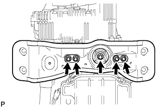
Remove the 5 nuts, No. 3 mounting insulator and rear engine mounting member.
-
-
REMOVE REAR NO. 1 ENGINE MOUNTING INSULATOR
Tech Tips
Only perform this procedure when replacement of the rear No. 1 engine mounting insulator is necessary.
-
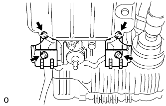
Remove the 4 bolts and 2 rear No. 1 engine mounting insulators.
-
-
REMOVE REAR NO. 2 ENGINE MOUNTING INSULATOR
Tech Tips
Only perform this procedure when replacement of the rear No. 2 engine mounting insulator is necessary.
-
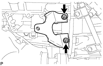
Remove the 2 bolts and rear No. 2 engine mounting insulator.
-
-
REMOVE OIL COOLER TUBE SUB-ASSEMBLY
-
Remove the 3 bolts and 2 clips and disconnect the oil cooler tube.
-
-
REMOVE OUTLET NO. 1 HYBRID WATER PUMP PIPE (for LHD)
-
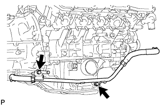
Remove the 2 bolts and outlet No. 1 hybrid water pump pipe.
-
-
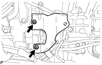
REMOVE STARTER HOLE INSULATOR
-
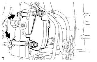
Remove the 2 bolts and starter hole insulator.
-
-
REMOVE HYBRID VEHICLE TRANSMISSION ASSEMBLY
-
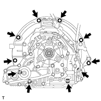
Remove the 10 bolts and hybrid vehicle transmission assembly.
Note
Do not use excessive force to pry out the transmission assembly when separating it from the engine to prevent the knock pins from being damaged.
-
-
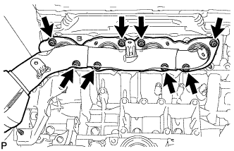
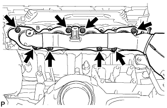
REMOVE INPUT TRANSMISSION DAMPER COVER ASSEMBLY
-
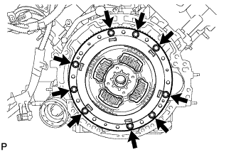
Remove the 9 bolts and input transmission damper cover assembly.
-
-
REMOVE FLYWHEEL SUB-ASSEMBLY
-
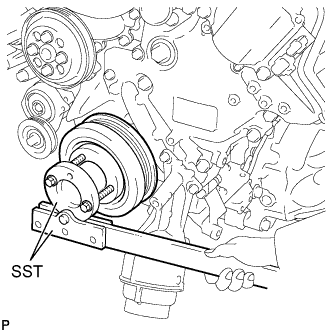
Using SST, hold the crankshaft.
- SST
- 09213-54015 ( 90119-08216 )
- 09330-00021
-
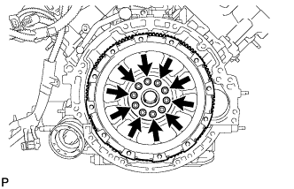
Remove the 10 bolts, crankshaft angle sensor plate and flywheel sub-assembly.
-
-
INSTALL ENGINE TO ENGINE STAND
-
Install the engine onto an engine stand with the bolts.
Note
-
Pay attention to the angle of the sling device as the engine assembly or engine hangers may be damaged or deformed if the angle is incorrect.
-
With the exception of installing the engine assembly to an engine stand or removing the engine assembly from an engine stand, do not perform any work on the engine while it is suspended, as doing so is dangerous.
-
-
Remove the 2 bolts and 2 engine hangers.
-