CAMSHAFT (for Bank 2) INSTALLATION

-
INSTALL CAMSHAFT BEARING CAP RH
-
Apply a light coat of engine oil to the camshaft journals, camshaft housings and bearing caps.
-
Install the No. 1 and No. 2 camshafts to the camshaft housing.
-
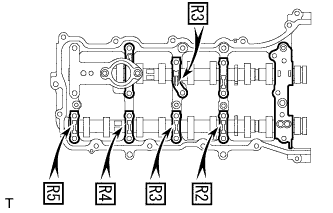
Confirm the marks and numbers on the camshaft bearing caps and place them each in their proper positions and directions.
-

Temporarily install the 8 bolts in the order shown in the illustration.
-
-
INSTALL CAMSHAFT HOUSING SUB-ASSEMBLY RH
-
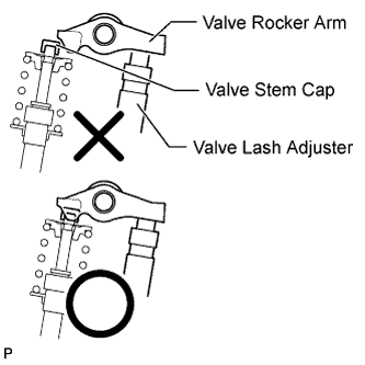
Make sure that the valve rocker arms are installed as shown in the illustration.
-
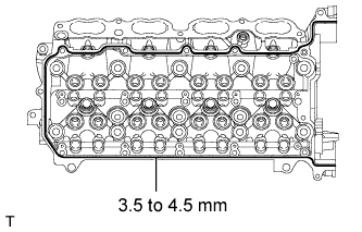
Apply seal packing in a continuous line as shown in the illustration.
Seal packing Toyota Genuine Seal Packing Black, Three Bond 1207B or equivalent Standard seal diameter 3.5 to 4.5 mm (0.138 to 0.177 in.) Note
-
Remove any oil from the contact surface.
-
Install the camshaft housing within 3 minutes and tighten the bolts within 10 minutes after applying seal packing.
-
-
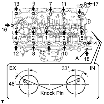
Install the camshaft housing, and install the 18 bolts in the order shown in the illustration.
- Torque:
- for bolt A
- 10 N*m { 102 kgf*cm, 7 ft.*lbf }
- except bolt A
- 30 N*m { 306 kgf*cm, 22 ft.*lbf }
Note
-
Do not start the engine for at least 2 hours after the installation.
-
Make sure that the knock pin of the camshaft is positioned as shown in the illustration before installing the camshaft housing.
-
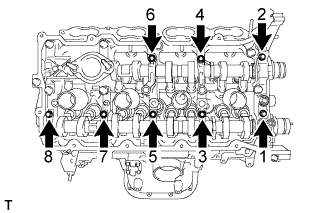
Tighten the 8 bolts in the order shown in the illustration.
- Torque:
- 16 N*m { 163 kgf*cm, 12 ft.*lbf }
Note
Thoroughly wipe clean any seal packing.
-
-
SET NO. 1 CYLINDER TO TDC / COMPRESSION
-
Temporarily install the crankshaft pulley bolt.
-
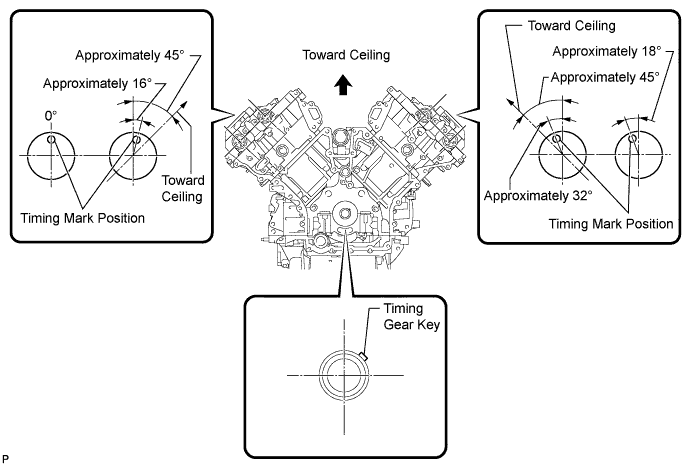
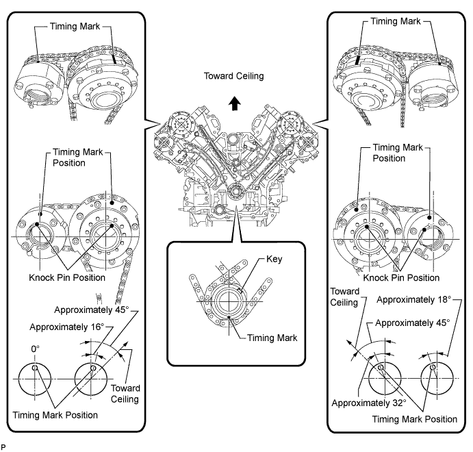
Rotate the crankshaft so that the timing gear key is as shown in the illustration. Then using a wrench, rotate each camshaft so that the timing marks are as shown in the illustration.
Note
When the crankshaft or a camshaft is rotated excessively, the valves and pistons may interfere with each other.
-
Remove the crankshaft pulley bolt.
-
-
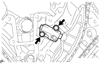
INSTALL NO. 2 CHAIN TENSIONER ASSEMBLY
-
Install the chain tensioner with the 2 bolts.
- Torque:
- 10 N*m { 102 kgf*cm, 7 ft.*lbf }
-
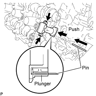
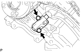
While raising up the No. 2 chain tensioner, insert a pin with a diameter of 1.0 mm (0.0394 in.) into the hole to fix it in place.
-
-
INSTALL NO. 1 CHAIN SUB-ASSEMBLY RH
-
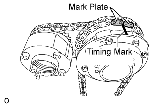
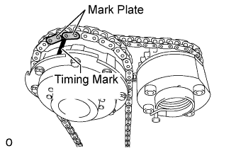
Align the No. 1 chain's orange mark plates with the camshaft timing gear's timing mark, and attach the chain to the gear as shown in the illustration.
-
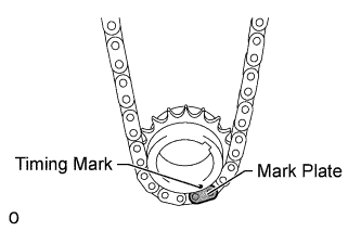
Align the No. 1 chain's orange mark plate with the crankshaft timing gear's timing mark, and attach the chain to the gear as shown in the illustration.
-
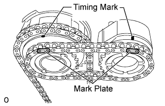
Align the No. 2 chain's yellow mark plates with the timing marks of the camshaft timing gear assembly and camshaft timing exhaust gear assembly, and attach the No. 2 chain to the gears as shown in the illustration.
Tech Tips
The crankshaft timing sprocket RH and camshaft exhaust gear will be installed with the No. 1 and No. 2 chains connected to the gears.
-
Install the crankshaft timing sprocket RH to the crankshaft.
-
Align and attach the knock pin of the No. 1 camshaft with the pin hole of the camshaft timing gear.
-
Using the hexagonal portion of the No. 2 camshaft, align and attach the knock pin of the No. 2 camshaft with the pin hole of the camshaft timing exhaust gear.
-
Remove the pin from the No. 2 chain tensioner.
-
Using a wrench to hold the hexagonal portion of the No. 1 camshaft, temporarily install a new bolt, with a 12 mm socket hexagon wrench.
-
Using a wrench to hold the hexagonal portion of the No. 2 camshaft, temporarily install the bolt.
-
-
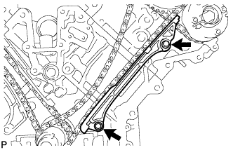
INSTALL NO. 1 CHAIN VIBRATION DAMPER RH
-
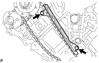
Install the vibration damper with the 2 bolts.
- Torque:
- 21 N*m { 214 kgf*cm, 15 ft.*lbf }
-
-
INSTALL NO. 1 CHAIN TENSIONER SLIPPER RH
Tech Tips
If you cannot install the chain tensioner slipper due to the tension of the chain, use the hexagonal portion of the camshaft to loosen the chain, and then install the chain tensioner slipper.
-
INSTALL NO. 1 CHAIN TENSIONER ASSEMBLY RH
-
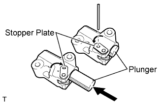
Move the stopper plate clockwise to release the lock, and push the plunger deep into the tensioner.
-
Move the stopper plate counterclockwise to set the lock, and insert a hexagon wrench into the hole of the stopper plate.
-
Install the chain tensioner with the 2 bolts.
- Torque:
- 10 N*m { 102 kgf*cm, 7 ft.*lbf }
-
Remove the hexagon wrench from the chain tensioner.
-
-
INSTALL NO. 1 CHAIN SUB-ASSEMBLY LH
-
Align the No. 1 chain's orange mark plates with the camshaft timing gear's timing mark, and attach the chain to the gear as shown in the illustration.
-
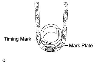
Align the No. 1 chain's orange mark plate with the crankshaft timing gear's timing mark, and attach the chain to the gear as shown in the illustration.
-
Align the No. 2 chain's yellow mark plates with the timing marks of the camshaft timing gear assembly and camshaft timing exhaust gear assembly, and attach the No. 2 chain to the gears as shown in the illustration.
Tech Tips
The crankshaft timing sprocket LH and camshaft exhaust gear will be installed with the No. 1 and No. 2 chains connected to the gears.
-
Install the crankshaft timing sprocket LH to the crankshaft.
-
Align and attach the knock pin of the No. 3 camshaft with the pin hole of the camshaft timing gear.
-
Using the hexagonal portion of the No. 4 camshaft, align and attach the knock pin of the No. 4 camshaft with the pin hole of the camshaft timing exhaust gear.
Note
Because the gears' timing mark positions may shift due to looseness of the No. 1 chain, use the hexagonal portion of the camshaft to hold the No. 3 camshaft in place until the No. 1 chain tensioner is installed.
-
Remove the pin from the No. 2 chain tensioner.
-
Using a wrench to hold the hexagonal portion of the No. 3 camshaft, temporarily install a new bolt, with a 12 mm socket hexagon wrench.
-
Using a wrench to hold the hexagonal portion of the No. 4 camshaft, temporarily install the bolt.
-
-
INSTALL NO. 1 CHAIN TENSIONER SLIPPER LH
Tech Tips
If you cannot install the chain tensioner slipper due to the tension of the chain, use the hexagonal portion of the camshaft to loosen the chain, and then install the chain tensioner slipper.
-
INSTALL NO. 1 CHAIN TENSIONER ASSEMBLY LH
-
Move the stopper plate clockwise to release the lock, and push the plunger deep into the tensioner.
-
Move the stopper plate counterclockwise to set the lock, and insert a hexagon wrench into the hole of the stopper plate.
-
Install the chain tensioner and a new gasket with the 2 bolts.
- Torque:
- 10 N*m { 102 kgf*cm, 7 ft.*lbf }
-
-
INSTALL NO. 1 CHAIN VIBRATION DAMPER LH
-
Install the vibration damper with the 2 bolts.
- Torque:
- 21 N*m { 214 kgf*cm, 15 ft.*lbf }
-
Remove the hexagon wrench from the No. 1 chain tensioner.
-
-
TIGHTEN CAMSHAFT TIMING GEAR ASSEMBLY
-
for Bank 1:
-
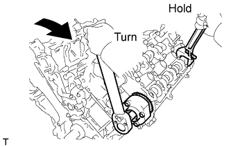
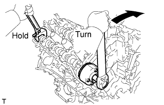
Using a wrench, hold the hexagonal portion of the No. 3 camshaft.
-
Using a 12 mm socket hexagon wrench, tighten the bolt of the camshaft timing gear.
- Torque:
- 79 N*m { 806 kgf*cm, 58 ft.*lbf }
-
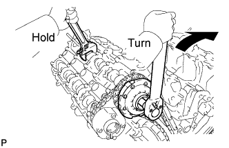
Using a wrench to hold the hexagonal portion of the No. 4 camshaft, tighten the bolt of the camshaft timing exhaust gear.
- Torque:
- 100 N*m { 1020 kgf*cm, 74 ft.*lbf }
-
-
for Bank 2:
-
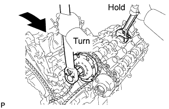
Using a wrench, hold the hexagonal portion of the No. 1 camshaft.
-
Using a 12 mm socket hexagon wrench, tighten the bolt of the camshaft timing gear.
- Torque:
- 79 N*m { 806 kgf*cm, 58 ft.*lbf }
-
Using a wrench to hold the hexagonal portion of the No. 2 camshaft, tighten the bolt of the camshaft timing exhaust gear.
- Torque:
- 100 N*m { 1020 kgf*cm, 74 ft.*lbf }
-
-
-
CHECK NO. 1 CYLINDER TO TDC / COMPRESSION
-
Temporarily install the crankshaft pulley bolt.
-
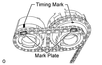
Rotate the crankshaft clockwise, and check that the timing marks on the crankshaft timing gear and camshaft timing gears are as shown in the illustration.
-
Remove the crankshaft pulley bolt.
-
-
INSTALL TIMING CHAIN COVER SUB-ASSEMBLY