CAMSHAFT (for Bank 2) INSPECTION

-
INSPECT CAMSHAFT TIMING GEAR ASSEMBLY
-
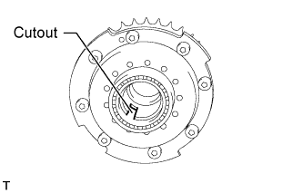
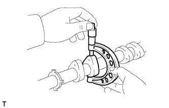
Using a vernier caliper, measure the width of the camshaft timing gear assembly's eccentric shaft cutout.
Standard width 6.0 to 6.2 mm (0.236 to 0.244 in.) Maximum width 6.7 mm (0.264 in.) If the result is greater than the maximum value, replace the camshaft timing gear assembly.
-
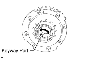
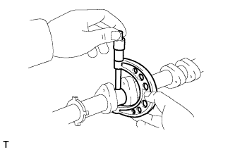
Check that the keyway part of the camshaft timing gear assembly's eccentric shaft rotates smoothly when the eccentric shaft is rotated by hand.
OK Rotates smoothly If the result is not as specified, replace the camshaft timing gear assembly.
Note
-
Do not drop the camshaft timing gear assembly. If dropped, replace it.
-
Do not disassemble the camshaft timing gear assembly. If disassembled, replace it.
-
-
-
INSPECT CAMSHAFT TIMING EXHAUST GEAR ASSEMBLY
-
Install the camshaft bearing caps Click here.
Tech Tips
Only install the exhaust camshaft.
-
Install the camshaft housing Click here.
-
Apply a light coat of engine oil to the camshaft and camshaft timing exhaust gear.
-
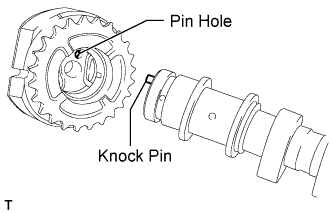
Using the hexagonal portion of the camshaft, align and attach the knock pin of the camshaft with the pin hole of the camshaft timing exhaust gear.
Note
-
Do not forcefully push on the camshaft timing exhaust gear. This may cause the camshaft knock pin tip to damage the installation surface of the camshaft timing exhaust gear.
-
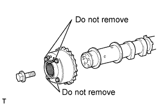
Be sure not to remove the other 4 bolts. If removed, replace the camshaft timing exhaust gear.
-
-
Apply a light coat of engine oil to the threads and under the heads of the bolt.
-
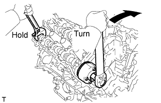
Using a wrench to hold the hexagonal portion of the camshaft, install the camshaft timing exhaust gear with the bolt.
- Torque:
- 100 N*m { 1020 kgf*cm, 74 ft.*lbf }
-
Remove the camshaft bearing caps Click here.
-
Check the lock of the camshaft timing exhaust gear.
-
Make sure that the camshaft timing exhaust gear is locked.
-
-
Release the lock pin.
-
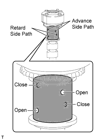
Cover the 4 oil paths of the cam journal with vinyl tape as shown in the illustration.
-
Prick a hole in the tape placed on the advance side path. Prick a hole in the tape placed on the retard side path on the opposite side to that of the advance side path, as shown in the illustration.
-
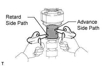
Apply approximately 200 kPa (2.0 kgf/cm2, 28 psi) of air pressure to the 2 broken paths (the advance side path and the retard side path).
CAUTION:
Cover the paths with a piece of cloth when applying pressure to keep oil from splashing.
-
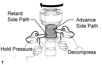
Check that the camshaft timing exhaust gear revolves in the retard direction when reducing the air pressure applied to the advance side path.
Tech Tips
This operation releases the lock pin for the most retarded position.
-
When the camshaft timing exhaust gear reaches the most retarded position, release the air pressure from the advance side path and retard side path, in that order.
Note
Do not release the air pressure from the retard side path first. The gear may abruptly shift in the advance direction and break the lock pin.
-
-
Check for smooth rotation.
-
Turn the camshaft timing exhaust gear within its movable range (18.5°) 2 or 3 times, but do not turn it to the most advanced position. Make sure that the gear turns smoothly.
Note
Do not use air pressure to perform the smooth rotation check.
-
-
Check the lock in the most advanced position.
-
Confirm that the camshaft timing gear is locked at the most advanced position.
-
-
Install the camshaft bearing caps Click here.
Tech Tips
Only install the exhaust camshaft.
-
Install the camshaft housing Click here.
-
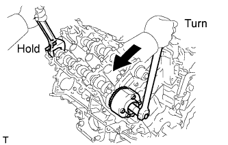
Hold the hexagonal portion of the camshaft with a wrench and loosen the bolt.
-
Remove the camshaft bearing caps Click here.
-
Remove the bolt and camshaft timing exhaust gear.
-
-
INSPECT CAMSHAFT
-
Inspect the camshaft for runout.
-
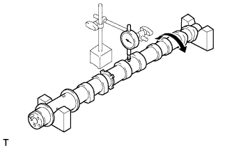
Place the camshaft on V-blocks.
-
Using a dial indicator, measure the circle runout at the center journal.
Maximum circle runout 0.04 mm (0.00157 in.) If the circle runout is greater than the maximum, replace the camshaft sub-assembly.
Tech Tips
Check the oil clearance after replacing the camshaft.
-
-
Using a micrometer, measure the cam lobe height.
Standard cam lobe height Item Specified Condition Intake 44.293 to 44.443 mm (1.744 to 1.750 in.) Exhaust 44.316 to 44.466 mm (1.745 to 1.751 in.) Minimum cam lobe height Item Specified Condition Intake 44.243 mm (1.742 in.) Exhaust 44.266 mm (1.743 in.) If the cam lobe height is less than the minimum, replace the camshaft sub-assembly.
-
Using a micrometer, measure the journal diameter.
Standard journal diameter Item Specified Condition No. 1 journal 29.956 to 29.970 mm (1.179 to 1.180 in.) Other journals 25.959 to 25.975 mm (1.022 to 1.023 in.) If the journal diameter is not as specified, check the oil clearance.
-
-
INSPECT CAMSHAFT OIL CLEARANCE
-
Clean the bearing caps, camshaft housing and camshaft journals.
-
Place the camshafts on the camshaft housing.
-
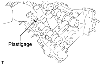
Lay a strip of Plastigage across each of the camshaft journals.
-
Install the camshaft bearing caps Click here.
Note
Do not turn the camshaft.
-
Install the camshaft housing Click here.
Note
Do not turn the camshaft.
-
Remove the camshaft bearing caps Click here.
-
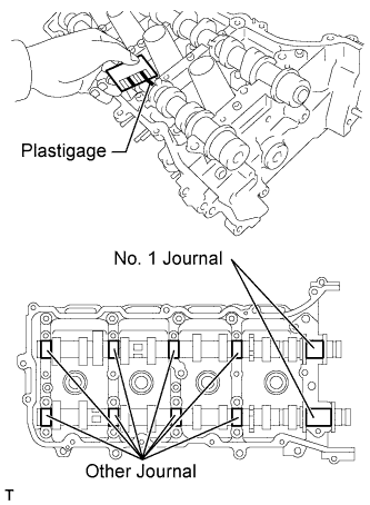
Measure the Plastigage at its widest point.
Standard oil clearance Item Specified Condition No. 1 Journal 0.030 to 0.065 mm (0.00118 to 0.00256 in.) Other Journals 0.025 to 0.062 mm (0.000984 to 0.00244 in.) Maximum oil clearance Item Specified Condition No. 1 journal 0.09 mm (0.00354 in.) Other journals 0.09 mm (0.00354 in.) If the oil clearance is greater than the maximum, replace the camshaft. If necessary, replace the camshaft housing.
-