ENGINE UNIT INSPECTION

Tech Tips
When viewed from the rear of the engine assembly, Bank 1 is on the left side and Bank 2 is on the right side.
-
INSPECT NO. 1 VALVE ROCKER ARM SUB-ASSEMBLY
-
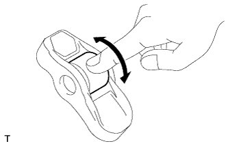
Turn the roller by hand to check that it turns smoothly.
If the roller does not turn smoothly, replace the No. 1 valve rocker arm.
-
-
INSPECT VALVE LASH ADJUSTER ASSEMBLY
Note
-
Keep the adjuster free from dirt and foreign objects.
-
Use only clean engine oil.
-
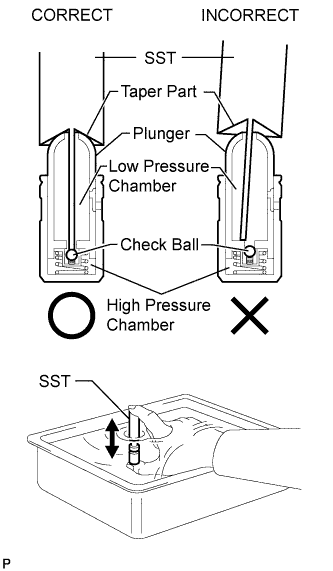
Place the lash adjuster into a container full of new engine oil.
-
Insert SST's tip into the lash adjuster's plunger and use the tip to press down on the check ball inside the plunger.
- SST
- 09276-75010
-
Squeeze SST and the lash adjuster together to move the plunger up and down 5 to 6 times.
-
Check the movement of the plunger and bleed air.
OK Plunger moves up and down. Note
When bleeding high-pressure air from the compression chamber, make sure that the tip of SST is actually pressing the check ball as shown in the illustration. If the check ball is not pressed, air will not bleed.
-
After bleeding the air, remove SST. Then try to quickly and firmly press the plunger with your fingers.
OK Plunger can be pressed 3 times. If the plunger can still be compressed after pressing it 3 times, replace the valve lash adjuster with a new one.
-
-
INSPECT CYLINDER HEAD SET BOLT
-
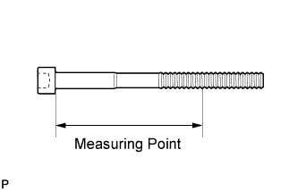
Using a vernier caliper, measure the minimum diameter of the elongated thread at the measuring point.
Measuring point 90 mm (3.54 in.) for intake side bolt 85 mm (3.35 in.) for exhaust side bolt Standard outside diameter 10.85 to 11.00 mm (0.427 to 0.433 in.) Minimum outside diameter 10.6 mm (0.417 in.) If the diameter is less than the minimum, replace the cylinder head set bolt.
Tech Tips
If a visual check reveals no excessively thin areas, check the center of the bolt (see illustration) and find the area that has the lowest diameter.
-
-
INSPECT CAMSHAFT
-
Inspect the bank 1 camshaft Click here.
-
Inspect the bank 2 camshaft Click here.
-
-
INSPECT CAMSHAFT TIMING GEAR ASSEMBLY
-
Inspect the bank 1 camshaft timing gear Click here.
-
Inspect the bank 2 camshaft timing gear Click here.
-
-
INSPECT CAMSHAFT TIMING EXHAUST GEAR ASSEMBLY
-
Inspect the bank 1 camshaft timing exhaust gear Click here.
-
Inspect the bank 2 camshaft timing exhaust gear Click here.
-
-
INSPECT NO. 1 CHAIN SUB-ASSEMBLY
-
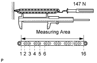
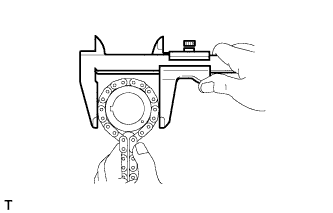
Using a spring scale, pull the chain with a force of 147 N (15 kgf, 33.0 lbf) as shown in the illustration.
-
Using a vernier caliper, measure the length of 15 pins.
Maximum chain elongation 136.9 mm (5.39 in.) If the elongation is greater than the maximum, replace the No. 1 chain.
Note
Perform the measurement at 3 random places.
-
-
INSPECT NO. 2 CHAIN SUB-ASSEMBLY
-
Using a spring scale, pull the chain with a force of 147 N (15 kgf, 33.0 lbf) as shown in the illustration.
-
Using a vernier caliper, measure the length of 15 pins.
Maximum chain elongation 137.6 mm (5.42 in.) If the elongation is greater than the maximum, replace the No. 2 chain.
Note
Perform the measurement at 3 random places.
-
-
INSPECT CRANKSHAFT TIMING SPROCKET RH
-

Wrap the chain around the sprocket.
-
Using a vernier caliper, measure the sprocket diameter with the chain.
Minimum sprocket diameter (w/ chain) 61.4 mm (2.42 in.) If the diameter is less than the minimum, replace the chain and crankshaft timing sprocket RH.
Tech Tips
The vernier caliper must contact the chain rollers for the measurement.
-
-
INSPECT CRANKSHAFT TIMING SPROCKET LH
-
Wrap the chain around the sprocket.
-
Using a vernier caliper, measure the sprocket diameter with the chain.
Minimum sprocket diameter (w/ chain) 61.4 mm (2.42 in.) If the diameter is less than the minimum, replace the chain and crankshaft timing sprocket LH.
Tech Tips
The vernier caliper must contact the chain rollers for the measurement.
-
-
INSPECT NO. 1 CHAIN TENSIONER ASSEMBLY
-
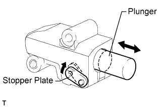
Move the stopper plate clockwise to release the lock. Push the plunger and check that it moves smoothly.
If necessary, replace the No. 1 chain tensioner.
-
-
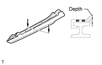
INSPECT NO. 2 CHAIN TENSIONER ASSEMBLY
-
Check that the plunger moves smoothly.
-
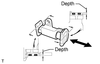
Measure the worn depth of the chain tensioner.
Maximum depth 0.9 mm (0.0354 in.) If the depth is greater than the maximum, replace the No. 2 chain tensioner.
-
-
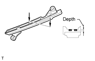
INSPECT NO. 3 CHAIN TENSIONER ASSEMBLY
-
Check that the plunger moves smoothly.
-
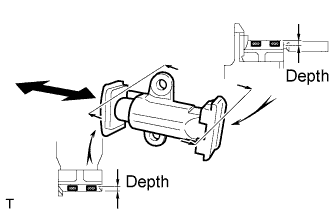
Measure the worn depth of the chain tensioner.
Maximum depth 0.9 mm (0.0354 in.) If the depth is greater than the maximum, replace the No. 3 chain tensioner.
-
-
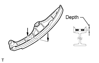
INSPECT NO. 1 CHAIN TENSIONER SLIPPER
-
for LH:
-
Measure the worn depth of the chain tensioner slipper.
Maximum depth 1.0 mm (0.0394 in.) If the depth is greater than the maximum, replace the No. 1 chain tensioner slipper.
-
-
for RH:
-
Measure the worn depth of the chain tensioner slipper.
Maximum depth 1.0 mm (0.0394 in.) If the depth is greater than the maximum, replace the No. 1 chain tensioner slipper.
-
-
-
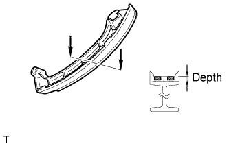
INSPECT NO. 1 CHAIN VIBRATION DAMPER
-
for LH:
-
Measure the worn depth of the chain vibration damper.
Maximum depth 1.0 mm (0.0394 in.) If the depth is greater than the maximum, replace the No. 1 chain vibration damper.
-
-
for RH:
-
Measure the worn depth of the chain vibration damper.
Maximum depth 1.0 mm (0.0394 in.) If the depth is greater than the maximum, replace the No. 1 chain vibration damper.
-
-
-
INSPECT CYLINDER HEAD SUB-ASSEMBLY
-
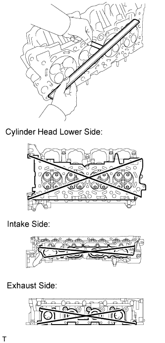
Using a precision straightedge and feeler gauge, measure the warpage of the surfaces where the cylinder head contacts the cylinder block and manifold.
Standard warpage Item Specified Condition Cylinder head lower side 0.05 mm (0.00197 in.) Intake side 0.08 mm (0.00315 in.) Exhaust side 0.05 mm (0.00197 in.) Maximum warpage 0.10 mm (0.00394 in.) If the warpage is greater than the maximum, replace the cylinder head.
-
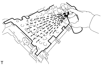
Using a dye penetrant, check the intake ports, exhaust ports and cylinder surface for cracks.
If cracked, replace the cylinder head.
-
-
INSPECT CAMSHAFT OIL CLEARANCE
-
Inspect the bank 1 camshaft oil clearance Click here.
-
Inspect the bank 2 camshaft oil clearance Click here.
-
-
INSPECT EXHAUST MANIFOLD SUB-ASSEMBLY LH
-
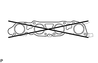
Using a precision straightedge and feeler gauge, measure the warpage of the surface where the exhaust manifold LH contacts the cylinder head.
Maximum warpage 0.7 mm (0.0276 in.) If the warpage is greater than the maximum, replace the exhaust manifold LH.
-
-
INSPECT EXHAUST MANIFOLD SUB-ASSEMBLY RH
-
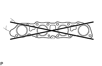
Using a precision straightedge and feeler gauge, measure the warpage of the surface where the exhaust manifold RH contacts the cylinder head.
Maximum warpage 0.7 mm (0.0276 in.) If the warpage is greater than the maximum, replace the exhaust manifold RH.
-