When viewed from the rear of the engine assembly, Bank 1 is on the left side and Bank 2 is on the right side.
- Click here
REMOVE V-RIBBED BELT
-
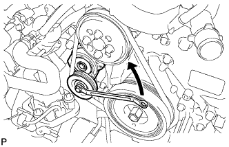
Rotate the tensioner pulley counterclockwise to loosen the V-ribbed belt tension assembly.
Tip:The pulley bolt for the V-ribbed belt tensioner assembly has a left-handed thread.
-
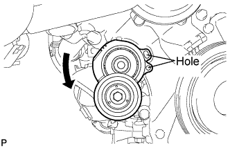
While turning the V-ribbed belt tensioner assembly counterclockwise, align the holes. Insert a bar with a diameter of 5 mm (0.197 in.) into the holes to fix the V-ribbed belt tensioner assembly in place.
-
Remove the V-ribbed belt.
-
- Click here
REMOVE WITH MOTOR COMPRESSOR ASSEMBLY
-
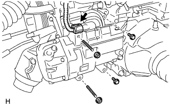
Disconnect the connector.
-
Remove the 2 bolts and 2 nuts.
-
Using an E8 ''TORX'' socket wrench, remove the 2 stud bolts and with motor compressor assembly.
-
- Click here
REMOVE FRONT DIFFERENTIAL CARRIER ASSEMBLY
-
Support the front differential carrier assembly with a jack.
CAUTION:As the front differential carrier assembly is very heavy, securely support it with the jack.
-
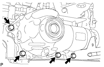
Remove the 4 bolts and front differential carrier assembly.
Note:
-
Do not damage the installation surface when removing the front differential carrier assembly.
-
The remaining oil may leak out when removing the front differential carrier assembly.
-
-
- Click here
REMOVE ENGINE COVER SUB-ASSEMBLY LH
-
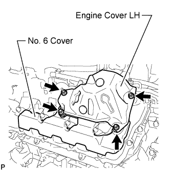
Remove the 4 nuts and engine cover LH.
-
- Click here
REMOVE NO. 6 COVER SUB-ASSEMBLY
-
Remove the No. 6 cover.
-
- Click here
REMOVE ENGINE COVER SUB-ASSEMBLY RH
-
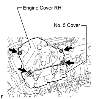
Remove the 4 nuts and engine cover RH.
-
- Click here
REMOVE NO. 5 COVER SUB-ASSEMBLY
-
Remove the No. 5 cover.
-
- Click here
REMOVE ENGINE WIRE
-
Engine LH Side:
-
Disconnect the camshaft timing control valve connector.
-
Disconnect the 4 ignition coil connectors.
-
Disconnect the 2 VVT sensor connectors.
-
Disconnect the fuel pump connector (for high pressure).
-
Disconnect the fuel injector connector.
-
Disconnect the 4 clamps.
-
-
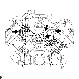
Engine Front Side:
-
Disconnect the engine coolant temperature sensor connector.
-
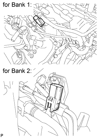
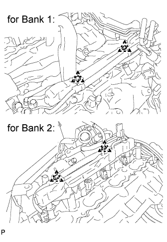
Disconnect the 2 camshaft timing control motor connectors (for Bank 1).
-
Disconnect the 2 camshaft timing control motor connectors (for Bank 2).
-
Disconnect the clamp.
-
Remove the 3 bolts and disconnect the 3 ground wires.
-
-
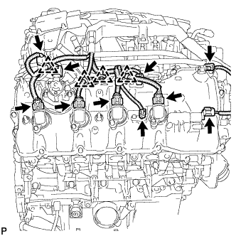
Engine RH Side:
-
Disconnect the camshaft timing control valve connector.
-
Disconnect the 4 ignition coil connectors.
-
Disconnect the 2 VVT sensor connectors.
-
Disconnect the fuel pump connector (for high pressure).
-
Disconnect the camshaft position sensor connector.
-
Disconnect the fuel injector connector.
-
Disconnect the 4 clamps.
-
-
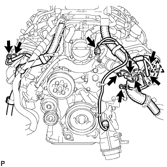
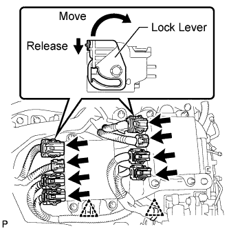
Engine Rear Side:
-
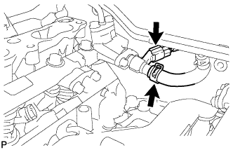
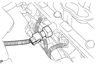
Disconnect the engine wire connector.
-
Disconnect the fuel relief valve connector.
-
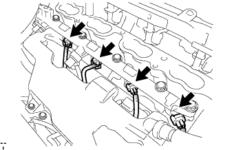
Disconnect the 8 clamps.
-
Remove the 2 bolts and disconnect the 2 ground wires.
-
-
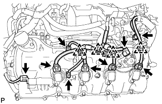
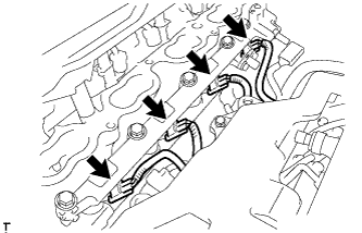
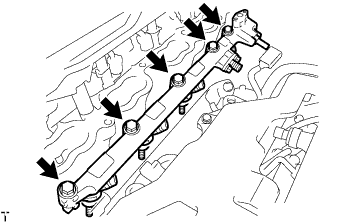
Engine Upper Side:
-
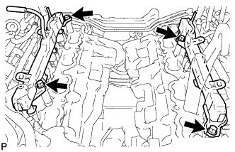
Disconnect the 8 injector connectors as shown in the illustration.
-
Disconnect the 2 clamps.
-
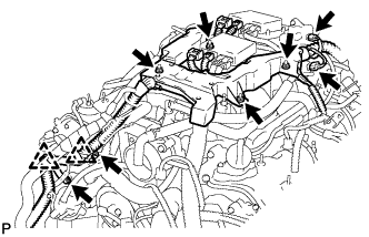
Disconnect the purge VSV connector.
-
Disconnect the intake air control valve actuator connector.
-
Disconnect the 2 clamps and remove the 2 bolts and 2 clamp brackets.
-
Remove the 4 nuts and remove the engine wire.
-
-
-
Click here
REMOVE INJECTOR DRIVER
-
Remove the 2 bolts, 2 nuts and 2 injector drivers with bracket.
Note:Be careful not to drop or strike the injector driver.
-
-
Click here
REMOVE NO. 1 ENGINE COVER
-
Click here
REMOVE PURGE VSV
-
Disconnect the purge line hose from the intake manifold.
-
Remove the bolt and purge VSV.
-
-
Click here
REMOVE HEATER WATER PUMP ASSEMBLY
-
Slide the 2 clamps, and disconnect the 2 hoses from the water inlet housing and water by-pass pipe.
-
Remove the bolt and heater water pump.
-
-
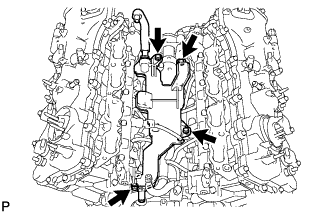
Click here
REMOVE WATER BY-PASS PIPE SUB-ASSEMBLY
-
Slide the clamp, and disconnect the water inlet hose from the front water by-pass joint.
-
Remove the 2 bolts and water by-pass pipe.
-
-
Click here
REMOVE INTAKE MANIFOLD ASSEMBLY
-
Disconnect the 2 water by-pass hoses and No. 1 ventilation hose as shown in the illustration.
-
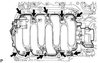
Remove the 8 bolts, 2 nuts and intake manifold.
-
Remove the 2 gaskets from the intake manifold.
-
-
Click here
REMOVE FUEL TUBE SUB-ASSEMBLY
-
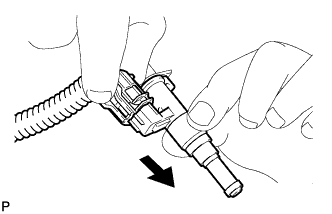
Lift up the retainer to release its lock.
-
Pinch the tube connector and then pull out the fuel tube.
Note:
-
Check for any dirt and foreign matter contamination in the pipe and around the connector. Clean if necessary. Foreign matter may damage the O-rings or cause leaks in the seal between the pipe and connector.
-
Do not use any tools to separate the pipe and connector.
-
Do not forcefully bend or twist the nylon tube.
-
Check for any dirt and foreign matter on the pipe seal surface. Clean if necessary.
-
Put the pipe and connector ends in plastic bags to prevent damage and dirt contamination.
-
If the pipe and connector are stuck together, pinch the tube between your fingers and turn it carefully to free it. Then disconnect the tube.
-
-
- Click here
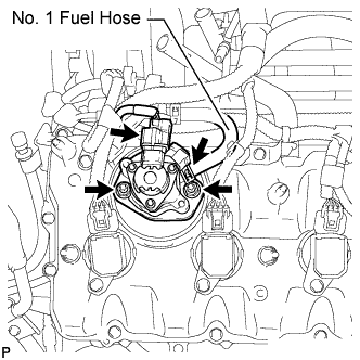
REMOVE FUEL PRESSURE PULSATION DAMPER ASSEMBLY
-
Disconnect the 2 delivery pipe connectors from the delivery pipe.
-
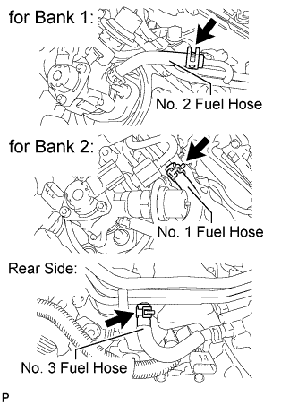
Disconnect the 3 fuel hoses.
-
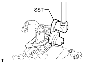
Using SST, remove the 2 fuel pressure pulsation dampers.
09612-24014 09617-24011 -
Remove the 2 clamp bolts shown in the illustration.
-
Remove the 2 pulsation dampers, 4 gaskets and No. 1 fuel pipe.
-
- Click here
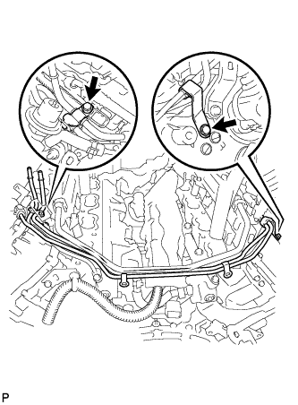
REMOVE NO. 3 FUEL PIPE SUB-ASSEMBLY
-
Disconnect the fuel pump connector.
-
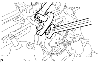
Fix the union bolt on the fuel pump side in place with a 21 mm wrench. Using a 19 mm union nut wrench, loosen the union nut and disconnect the No. 3 fuel pipe sub-assembly from the fuel pump.
Note:Do not loosen the union bolt on the fuel pump side. If the union bolt is accidentally loosened, replace the fuel pump.
-
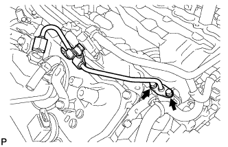
Remove the 2 bolts on the delivery pipe side and remove the No. 3 fuel pipe sub-assembly.
-
Remove the O-ring, backup rings and E-ring from the No. 3 fuel pipe sub-assembly.
-
- Click here
REMOVE NO. 2 FUEL PIPE SUB-ASSEMBLY
Tip:The removal procedures are the same as for the No. 3 fuel pipe sub-assembly.
- Click here
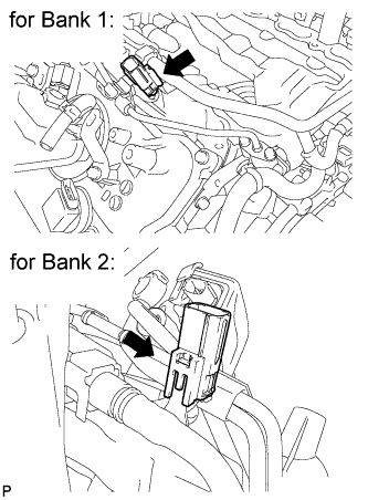
REMOVE FUEL PUMP ASSEMBLY (for Bank 1)
-
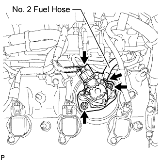
Disconnect the fuel pump connector.
-
Remove the 2 nuts, fuel pump and fuel pump insulator.
-
Disconnect the No. 2 fuel hose from the fuel pump.
-
- Click here
REMOVE FUEL PUMP ASSEMBLY (for Bank 2)
-
Disconnect the fuel pump connector.
-
Remove the 2 nuts, fuel pump and fuel pump insulator.
-
Disconnect the No. 1 fuel hose from the fuel pump.
-
- Click here
REMOVE WATER INLET HOUSING
-
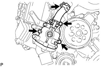
Using needle-nose pliers, grip the claws of the clip and slide the clip to disconnect the water inlet hose.
-
Remove the 3 bolts, water inlet housing and gasket.
-
- Click here
REMOVE FUEL DELIVERY PIPE ASSEMBLY
-
Disconnect the 2 delivery pipe connectors.
-
Disconnect the 4 wire harness clamps.
-
Remove the 4 bolts and 2 fuel delivery pipes.
Note:When removing the delivery pipe, hold the pipe by both ends and pull it straight upward.
-
Remove the 4 delivery pipe spacers and 8 insulators from the cylinder head.
-
- Click here
REMOVE FUEL INJECTOR ASSEMBLY (for Port Injection)
-
Remove the 8 fuel injectors from the fuel delivery pipes.
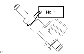
Note:For reinstallation, attach a tag or label to the injector shaft.
-
Disconnect the connector from the injector.
-

Remove the O-ring from the fuel injector.
-
-
Click here
REMOVE NO. 1 ENGINE COVER SUB-ASSEMBLY
-
Click here
REMOVE NO. 2 ENGINE COVER SUB-ASSEMBLY
-
Click here
REMOVE NO. 2 ENGINE COVER SUB-ASSEMBLY LH
- Click here
REMOVE NO. 4 FUEL PIPE SUB-ASSEMBLY
-
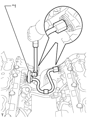
Using a 19 mm union nut wrench, remove the No. 4 fuel pipe sub-assembly.
Table 1. Text in Illustration *1 Union Nut Wrench
-
- Click here
REMOVE FUEL DELIVERY PIPE
-
Disconnect the fuel relief valve connector and No. 3 fuel hose.
-
Disconnect the 4 fuel injector connectors.
-
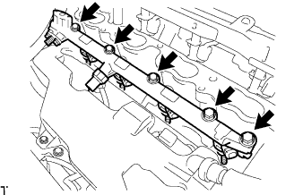
Remove the 5 bolts and fuel delivery pipe from the cylinder head.
Note:
-
Be extremely careful not to touch or strike the tips of the fuel injector assemblies.
-
Pull and remove the fuel delivery pipe in a straight line without tilting it.
-
-
Remove the 4 injector vibration insulators from the cylinder head.
-
- Click here
REMOVE NO. 2 FUEL DELIVERY PIPE
-
Disconnect the fuel pressure sensor connector.
-
Disconnect the 4 fuel injector connectors.
-
Remove the 5 bolts and No. 2 fuel delivery pipe from the cylinder head.
Note:
-
Be extremely careful not to touch or strike the tips of the fuel injector assemblies.
-
Pull and remove the No. 2 fuel delivery pipe in a straight line without tilting it.
-
-
Remove the 4 injector vibration insulators from the cylinder head.
-
- Click here
REMOVE FUEL INJECTOR ASSEMBLY (for Direct Injection)
-
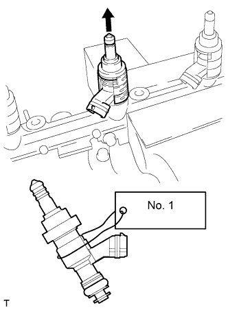
Secure the fuel delivery pipe between aluminum plates in a vise and pull out the fuel injector assembly in a straight line.
Note:
-
Do not overtighten the vise.
-
Pull and remove the fuel injector assembly in a straight line to avoid damage to the seal surface of the fuel delivery pipe's O-ring.
-
For reinstallation, attach a tag or label to the fuel injector assembly shaft.
-
-
Remove the nozzle holder clamp from the fuel injector assembly.
-
Remove the O-ring, No. 1 backup ring, No. 2 backup ring, No. 3 backup ring and E-ring from the fuel injector assembly.
-
- Click here
REMOVE FUEL INJECTOR SEAL
-
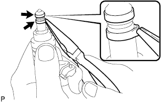
Using the tips of needle-nose pliers, pinch and pull one of the 2 fuel injector seals at several points to stretch it. Repeat this for the other fuel injector seal.
Note:
-
Excessively pinching the fuel injector seal may damage the groove of the fuel injector assembly.
-
If a fuel injector assembly is dropped or the tip of the fuel injector assembly is struck, replace it with a new one.
-
-
Remove the 2 fuel injector seals from the fuel injector assembly.
-
- Click here
REMOVE SEPARATOR CASE
-
Remove the 4 bolts and separator case.
-
-
Click here
REMOVE ENGINE WIRE
-
Disconnect the 4 connectors and 5 clamps.
-
Remove the bolt and engine wire.
-
-
Click here
REMOVE KNOCK CONTROL SENSOR
-
Remove the 4 bolts and 4 knock control sensors.
-
-
Click here
REMOVE IGNITION COIL ASSEMBLY
-
Remove the 8 bolts and 8 ignition coils.
-