INSPECTION PROCEDURE
PROCEDURE
- Click here
CHECK FUEL PUMP OPERATION
-
Check fuel pressure (see pageClick here).
Tip:If there is fuel pressure, you will hear the sound of fuel flowing.
- OKClick here
- NGClick here
-
- Click here
INSPECT FUEL PUMP RELAY (F/PMP)
-
Inspect the fuel pump relay (F/PMP) (see pageClick here).
- OKClick here
- NGClick here
-
-
Click here
INSPECT FUEL PUMP RESISTOR
-
Inspect the fuel pump resistor resistance.
-
Measure the resistance according to the value(s) in the table below.
Standard resistance Tester Connection Condition Specified Condition 1 - 2 20°C (68°F) 0.941 to 0.999 Ω
- OKClick here
- NGClick here
-
-
Click here
CHECK HARNESS AND CONNECTOR (CIRCUIT OPENING RELAY (C/OPN) TO FUEL PUMP)
-
Check the harness and connector.
-
Remove the circuit opening relay (C/OPN) and fuel pump relay (F/PMP) from the engine room No. 2 relay block.
-
Disconnect the A16 fuel pump resistor connector.
-
Measure the resistance according to the value(s) in the table below.
Standard resistance (Check for open) Tester Connection Condition Specified Condition C/OPN relay (3) - F/PMP relay (4) Always Below 1 Ω C/OPN relay (3) - A16-1 Always Below 1 Ω Standard resistance (Check for short) Tester Connection Condition Specified Condition C/OPN relay (3) or F/PMP relay (4) - Body ground Always 10 kΩ or higher C/OPN relay (3) or A16-1 - Body ground Always 10 kΩ or higher
-
-
Check the harness and connector.
-
Remove the F/PMP relay from the engine room No. 2 relay block.
-
Disconnect the A16 fuel pump resistor connector.
-
Disconnect the S11 fuel pump and fuel sender gauge connector.
-
Measure the resistance according to the value(s) in the table below.
Standard resistance (Check for open) Tester Connection Condition Specified Condition F/PMP relay (3) - S11-4 Always Below 1 Ω A16-2 - S11-4 Always Below 1 Ω Standard resistance (Check for short) Tester Connection Condition Specified Condition F/PMP relay (3) or S11-4 - Body ground Always 10 kΩ or higher A16-2 or S11-4 - Body ground Always 10 kΩ or higher
-
- OKClick here
- NGClick here
-
- Click here
PERFORM ACTIVE TEST USING INTELLIGENT TESTER (OPERATE CIRCUIT OPENING RELAY (C/OPN))
-
Connect the intelligent tester to the DLC3.
-
Turn the power switch on (IG) and turn the tester ON.
-
Enter the following menus: Powertrain / Engine and ECT / Active Test / Activate the Fuel Pump Speed Control.
-
Check whether operating sounds can be heard while operating the relay using the tester.
OK Operating sounds can be heard from relay.
- OKClick here
- NGClick here
-
- Click here
INSPECT EFI MAIN FUSE
-
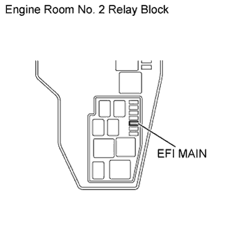
Remove the EFI MAIN fuse from the engine room No. 2 relay block.
-
Measure the resistance according to the value(s) in the table below.
Standard resistance Tester Connection Condition Specified Condition EFI MAIN fuse Always Below 1 Ω
- OKClick here
- NGClick here
-
- Click here
INSPECT EFI RELAY (EFI MAIN)
-
Inspect the EFI relay (EFI MAIN) (see pageClick here).
- OKClick here
- NGClick here
-
- Click here
CHECK HARNESS AND CONNECTOR (CIRCUIT OPENING RELAY (C/OPN) - EFI RELAY (EFI MAIN))
-
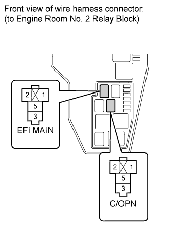
Remove the EFI relay (EFI MAIN) and the circuit opening relay (C/OPN) from the engine room No. 2 relay block.
-
Measure the resistance according to the value(s) in the table below.
Standard resistance (Check for open) Tester Connection Condition Specified Condition EFI MAIN relay (3) - C/OPN relay (5) Always Below 1 Ω Standard resistance (Check for short) Tester Connection Condition Specified Condition EFI MAIN relay (3) or C/OPN relay (5) - Body ground Always 10 kΩ or higher
- OKClick here
- NGClick here
-
- Click here
INSPECT FUEL PUMP RELAY (F/PMP)
-
Inspect the fuel pump relay (F/PMP) (see pageClick here).
- OKClick here
- NGClick here
-
-
Click here
INSPECT FUEL PUMP RESISTOR
-
Inspect the fuel pump resistor resistance.
-
Measure the resistance according to the value(s) in the table below.
Standard resistance Tester Connection Condition Specified Condition 1 - 2 20°C (68°F) 0.941 to 0.999 Ω
- OKClick here
- NGClick here
-
-
Click here
CHECK HARNESS AND CONNECTOR (CIRCUIT OPENING RELAY (C/OPN) TO FUEL PUMP)
-
Check the harness and connector.
-
Remove the circuit opening relay (C/OPN) and the fuel pump relay (F/PMP) from the engine room No. 2 relay block.
-
Disconnect the A16 fuel pump resistor connector.
-
Measure the resistance according to the value(s) in the table below.
Standard resistance (Check for open) Tester Connection Condition Specified Condition C/OPN relay (3) - F/PMP relay (4) Always Below 1 Ω C/OPN relay (3) - A16-1 Always Below 1 Ω Standard resistance (Check for short) Tester Connection Condition Specified Condition C/OPN relay (3) or F/PMP relay (4) - Body ground Always 10 kΩ or higher C/OPN relay (3) or A16-1 - Body ground Always 10 kΩ or higher
-
-
Check the harness and connector.
-
Remove the fuel pump relay (F/PMP) from the engine room No. 2 relay block.
-
Disconnect the A16 fuel pump resistor connector.
-
Disconnect the S11 fuel pump and fuel sender gauge connector.
-
Measure the resistance according to the value(s) in the table below.
Standard resistance (Check for open) Tester Connection Condition Specified Condition F/PMP relay (3) - S11-4 Always Below 1 Ω A16-2 - S11-4 Always Below 1 Ω Standard resistance (Check for short) Tester Connection Condition Specified Condition F/PMP relay (3) or S11-4 - Body ground Always 10 kΩ or higher A16-2 or S11-4 - Body ground Always 10 kΩ or higher
-
- OKClick here
- NGClick here
-
-
Click here
INSPECT FUEL PUMP ASSEMBLY
-
Inspect the fuel pump resistance.
-
Measure the resistance according to the value(s) in the table below.
Standard resistance Tester Connection Condition Specified Condition 1 - 2 20°C (68°F) 0.2 to 3.0 Ω
-
-
Inspect the fuel pump operation.
-
Apply battery voltage to both terminals. Check that the pump operates.
Note:
-
These tests must be done quickly (within 10 seconds) to prevent the coil from burning out.
-
Keep the fuel pump as far away from the battery as possible.
-
Always turn the voltage on and off on the battery side, not the fuel pump side.
-
-
- OKClick here
- NGClick here
-
-
Click here
CHECK HARNESS AND CONNECTOR (FUEL PUMP - BODY GROUND)
-
Disconnect the S11 fuel pump and fuel sender gauge connector.
-
Measure the resistance according to the value(s) in the table below.
Standard resistance Tester Connection Condition Specified Condition S11-5 - Body ground Always Below 1 Ω
- OKClick here
- NGClick here
-
- Click here
INSPECT CIRCUIT OPENING RELAY (C/OPN)
-
Inspect the circuit opening relay (C/OPN) (see pageClick here).
- OKClick here
- NGClick here
-
- Click here
CHECK HARNESS AND CONNECTOR (CIRCUIT OPENING RELAY (C/OPN) - EFI-B FUSE)
-
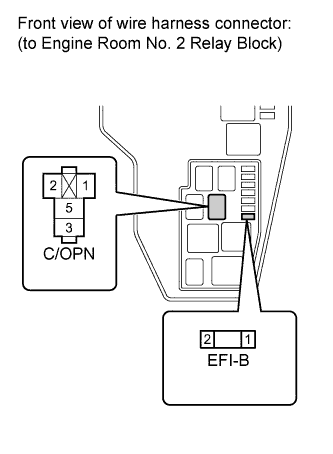
Remove the circuit opening relay (C/OPN) and EFI-B fuse from the engine room No. 2 relay block.
-
Measure the resistance according to the value(s) in the table below.
Standard resistance (Check for open) Tester Connection Condition Specified Condition C/OPN relay (1) - EFI-B fuse (2) Always Below 1 Ω Standard resistance (Check for short) Tester Connection Condition Specified Condition C/OPN relay (1) or EFI-B fuse (2) - Body ground Always 10 kΩ or higher
- OKClick here
- NGClick here
-
- Click here
CHECK CIRCUIT OPENING RELAY (C/OPN) (POWER SOURCE)
-
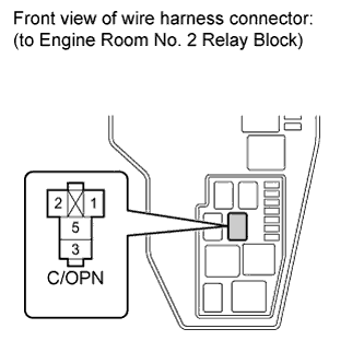
Remove the circuit opening relay (C/OPN) from the engine room No. 2 relay block.
-
Measure the voltage according to the value(s) in the table below.
Standard voltage Tester Connection Condition Specified Condition C/OPN relay (1) - Body ground Power switch on (IG) 11 to 14 V
- OKClick here
- NGClick here
-
- Click here
CHECK HARNESS AND CONNECTOR (CIRCUIT OPENING RELAY (C/OPN) - ECM)
-
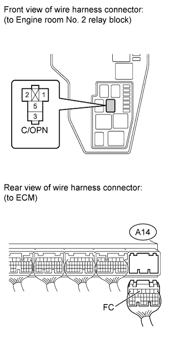
Remove the circuit opening relay (C/OPN) from the engine room No. 2 relay block.
-
Disconnect the A14 ECM connector.
-
Measure the resistance according to the value(s) in the table below.
Standard resistance (Check for open) Tester Connection Condition Specified Condition C/OPN relay (2) - A14-3 (FC) Always Below 1 Ω Standard resistance (Check for short) Tester Connection Condition Specified Condition C/OPN relay (2) or A14-3 (FC) - Body ground Always 10 kΩ or higher
- OKClick here
- NGClick here
-
- Click here
REPLACE FUEL PUMP RELAY (F/PMP)
- Click here
REPLACE FUEL PUMP RESISTORClick here
- Click here
REPAIR OR REPLACE HARNESS OR CONNECTOR
- Click here
CHECK FOR SHORT IN ALL HARNESSES AND CONNECTORS CONNECTED TO FUSE AND REPLACE FUSE
- Click here
REPLACE EFI RELAY (EFI MAIN)
- Click here
REPAIR OR REPLACE HARNESS OR CONNECTOR
- Click here
REPLACE FUEL PUMP RELAY (F/PMP)
- Click here
REPLACE FUEL PUMP RESISTORClick here
- Click here
REPAIR OR REPLACE HARNESS OR CONNECTOR
- Click here
REPLACE FUEL PUMPClick here
- Click here
REPAIR OR REPLACE HARNESS OR CONNECTOR
- Click here
REPLACE CIRCUIT OPENING RELAY (C/OPN)
- Click here
REPAIR OR REPLACE HARNESS OR CONNECTOR
- Click here
GO TO ECM POWER SOURCE CIRCUITClick here
- Click here
REPAIR OR REPLACE HARNESS OR CONNECTOR
- Click here
REPLACE ECMClick here
- Click here
REPAIR OR REPLACE HARNESS OR CONNECTOR (EFI MAIN RELAY - BATTERY)
- Click here
REPLACE ECMClick here