SFI SYSTEM, Diagnostic DTC:P2A00, P2A03

| DTC Code | DTC Name |
|---|---|
| P2A00 | A/F Sensor Circuit Slow Response (Bank 1 Sensor 1) |
| P2A03 | A/F Sensor Circuit Slow Response (Bank 2 Sensor 1) |
DESCRIPTION
Refer to DTC P2195 Click here.
Tech Tips
-
DTC P2A00 indicates malfunctions related to the bank 1 A/F sensor.
-
DTC P2A03 indicates malfunctions related to the bank 2 A/F sensor.
-
Bank 1 refers to the bank that includes No. 1 cylinder.
-
Bank 2 refers to the bank that includes No. 2 cylinder.
-
Sensor 1 refers to the sensor mounted in front of the Three-Way Catalytic Converter (TWC) and located near the engine assembly.
| DTC No. | DTC Detection Condition | Trouble Area |
|---|---|---|
| P2A00 P2A03 |
Calculated value for air-fuel ratio (A/F) sensor response rate deterioration level is less than threshold |
|
MONITOR DESCRIPTION
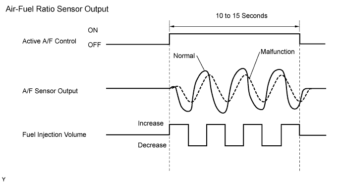
After engine is warmed up, the ECM performs air-fuel ratio feedback control to maintain the air-fuel ratio at the stoichiometric level. In addition, active A/F control is performed for 10 to 15 seconds after preconditions are met in order to measure the A/F sensor response rate. During active A/F control, the ECM forcibly increases and decreases the injection volume a certain amount, based on the stoichiometric air-fuel ratio learned during normal air-fuel ratio control, and measures the A/F sensor response rate. The ECM receives a signal from the A/F sensor while performing active A/F control and uses it to calculate the A/F sensor response rate deterioration level.
If the value for A/F sensor response rate deterioration level is less than the threshold, the ECM interprets this as a malfunction and sets the DTC.
CONFIRMATION DRIVING PATTERN
-
Connect the intelligent tester to the DLC3.
-
Turn the power switch on (IG).
-
Turn the intelligent tester on.
-
Clear the DTCs (even if no DTCs are stored, perform the clear DTC procedure) Click here.
-
Turn the power switch off and wait for at least 30 seconds.
-
Turn the power switch on (IG) and turn the intelligent tester on.
-
Put the engine in inspection mode (maintenance mode) Click here.
-
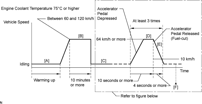
Start the engine, and warm it up until the engine coolant temperature reaches 75°C (167°F) or higher [A].
-
On the intelligent tester, enter the following menus to check the fuel-cut status: Powertrain / Engine and ECT / Data List / All Data / Idle Fuel Cut.
-
Drive the vehicle at between 60 and 120 km/h (37 and 75 mph) for at least 10 minutes [B].
CAUTION:
When performing the confirmation driving pattern, obey all speed limits and traffic laws.
-
With the shift lever in B position [C], accelerate the vehicle to 64 km/h (40 mph) or more by depressing the accelerator pedal for at least 10 seconds [D].
CAUTION:
When performing the confirmation driving pattern, obey all speed limits and traffic laws.
-
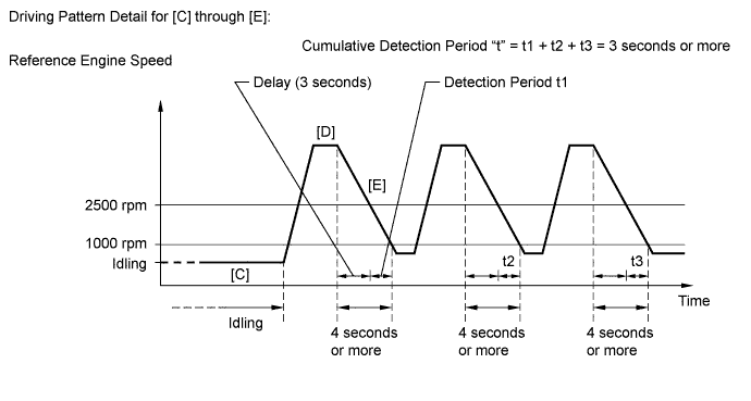
Soon after performing step [D] above, release the accelerator pedal for at least 4 seconds without depressing the brake pedal in order to execute fuel-cut control [E].
Tech Tips
Fuel-cut is performed when the following conditions are met:
-
Accelerator pedal is fully released.
-
Engine speed is 2500 rpm or more (fuel injection returns at 1400 rpm).
-
-
Allow the vehicle to decelerate until the vehicle speed decreases to less than 10 km/h (6 mph).
-
Repeat steps [C] through [E] above at least 3 times in one driving cycle.
-
Enter the following menus: Powertrain / Engine and ECT / DTC / Pending.
-
Read the pending DTC [F].
Tech Tips
-
If a pending DTC is output, the system is malfunctioning.
-
If a pending DTC is not output, perform the following procedure.
-
-
Enter the following menus: Powertrain / Engine and ECT / Utility / All Readiness.
-
Input the DTC: P2195, P2196, P2197 or P2198.
-
Check the DTC judgment result.
Tester Display Description NORMAL
-
DTC judgment completed
-
System normal
ABNORMAL
-
DTC judgment completed
-
System abnormal
INCOMPLETE
-
DTC judgment not completed
-
Perform driving pattern after confirming DTC enabling conditions
N/A
-
Unable to perform DTC judgment
-
Number of DTCs which do not fulfill DTC preconditions has reached ECU memory limit
Tech Tips
-
If the judgment result shows ABNORMAL, the system has a malfunction.
-
If the judgment result shows NORMAL, the system is normal.
-
If the judgment result shows INCOMPLETE or N/A, perform steps [B] through [F] again.
-
WIRING DIAGRAM
Refer to DTC P2195 Click here.
INSPECTION PROCEDURE
Tech Tips
-
DTC P2A00 or P2A03 may be also set, when the air-fuel ratio is stuck rich or lean.
-
A low A/F sensor voltage could be caused by a rich air-fuel mixture. Check for conditions that would cause the engine to run rich.
-
A high A/F sensor voltage could be caused by a lean air-fuel mixture. Check for conditions that would cause the engine to run lean.
-
Read freeze frame data using the intelligent tester. Freeze frame data records the engine condition when malfunctions are detected. When troubleshooting, freeze frame data can help determine if the vehicle was moving or stationary, if the engine was warmed up or not, if the air-fuel ratio was lean or rich, and other data from the time the malfunction occurred.
-
When viewed from the rear of the engine assembly, Bank 1 is on the left side and Bank 2 is on the right side.
PROCEDURE
-
CHECK ANY OTHER DTCS OUTPUT (IN ADDITION TO DTC P2A00 AND/OR P2A03)
-
Connect the intelligent tester to the DLC3.
-
Turn the power switch on (IG).
-
Turn the tester ON.
-
Enter the following menus: Powertrain / Engine and ECT / DTC.
-
Read DTCs.
Result Display (DTC Output) Proceed to P2A00 and/or P2A03 A P2A00 and/or P2A03 and other DTCs B Tech Tips
If any DTCs other than P2A00 or P2A03 are output, troubleshoot those DTCs first.
B 
GO TO DTC CHART Click here
A 
-
-
INSPECT AIR FUEL RATIO SENSOR (HEATER RESISTANCE)
-
Turn the power switch off.
-
Disconnect the A/F sensor connector.
-
Measure the resistance according to the value(s) in the table below.
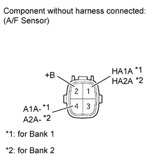
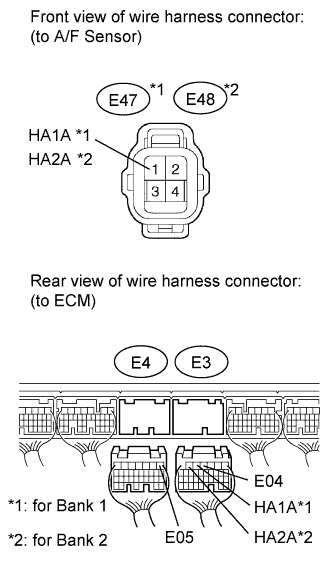
Standard resistance Bank 1 Sensor 1 Tester Connection Condition Specified Condition 1 (HA1A) - 2 (+B) 20°C (68°F) 1.8 to 3.4 Ω 1 (HA1A) - 4 (A1A-) Always 10 kΩ or higher Bank 2 Sensor 1 Tester Connection Condition Specified Condition 1 (HA2A) - 2 (+B) 20°C (68°F) 1.8 to 3.4 Ω 1 (HA2A) - 4 (A2A-) Always 10 kΩ or higher
NG
REPLACE AIR FUEL RATIO SENSOR Click here
OK
-
-
CHECK HARNESS AND CONNECTOR (A/F SENSOR - ECM)
-
Turn the power switch off.
-
Disconnect the E3 and E4 ECM connectors.
-
Measure the resistance according to the value(s) in the table below.
Standard resistance (Check for open) Tester Connection Condition Specified Condition E47-1 (HA1A) - E3-5 (HA1A) Always Below 1 Ω E48-1 (HA2A) - E3-6 (HA2A) Always Below 1 Ω E3-4 (E04) - Body ground Always Below 1 Ω E4-1 (E05) - Body ground Always Below 1 Ω Standard resistance (Check for short) Tester Connection Condition Specified Condition E47-1 (HA1A) or E3-5 (HA1A) - Body ground Always 10 kΩ or higher E48-1 (HA2A) or E3-6 (HA2A) - Body ground Always 10 kΩ or higher
NG
REPAIR OR REPLACE HARNESS OR CONNECTOR
OK
-
-
PERFORM CONFIRMATION DRIVING PATTERN
NEXT
-
CHECK WHETHER DTC OUTPUT RECURS (DTC P2A00 AND/OR P2A03)
-
Connect the intelligent tester to the DLC3.
-
Turn the power switch on (IG) and turn the tester ON.
-
Enter the following menus: Powertrain / Engine and ECT / DTC / Pending.
-
Read the DTCs.
Result Display (DTC Output) Proceed to P2A00 and/or P2A03 A No output B
B
CHECK FOR INTERMITTENT PROBLEMS Click here
A
-
-
REPLACE AIR FUEL RATIO SENSOR
-
Replace the air fuel ratio sensor Click here.
NEXT
-
-
PERFORM CONFIRMATION DRIVING PATTERN
NEXT
-
CHECK WHETHER DTC OUTPUT RECURS (DTC P2A00 AND/OR P2A03)
-
Connect the intelligent tester to the DLC3.
-
Turn the power switch on (IG) and turn the tester ON.
-
Enter the following menus: Powertrain / Engine and ECT / DTC / Pending.
-
Read the DTCs.
Result Display (DTC Output) Proceed to No output A P2A00 and/or P2A03 B
B
CHECK EXTREMELY RICH OR LEAN ACTUAL AIR FUEL RATIO (REFER TO DTC P0171 PROCEDURE) Click here
A 
END
-