SFI SYSTEM Cooling Fan Circuit
DESCRIPTION
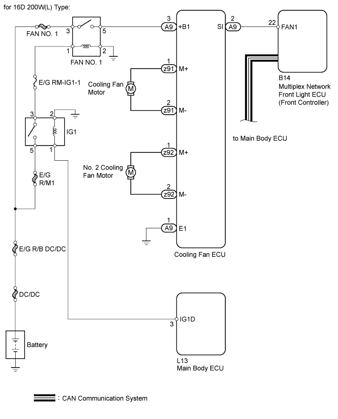
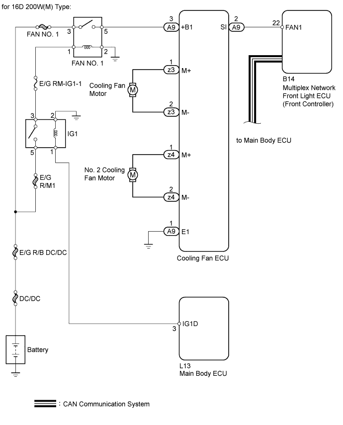
Based on the vehicle condition, the cooling fan ECU controls the cooling fan so that it operates at an optimum speed. The cooling fan ECU controls the cooling fan speed according to the duty ratio sent from the multiplex network front light ECU (front controller). The duty ratio is determined by selecting the highest speed from the fan speeds requested by the various ECUs via CAN communication.
WIRING DIAGRAM
INSPECTION PROCEDURE
PROCEDURE
-
PERFORM ACTIVE TEST USING INTELLIGENT TESTER
-
Connect the intelligent tester to the DLC3.
-
Turn the power switch on (IG).
-
Enter the following menus: Powertrain / Engine and ECT / Active Test / Control the Electric Cooling Fan.
-
Check the cooling fan operation.
OK Cooling fan operates according to the Active Test.
NG 
INSPECT COOLING FAN ECU (POWER SOURCE) Click here
OK 
CHECK FOR INTERMITTENT PROBLEMS Click here
-
-
INSPECT COOLING FAN ECU (POWER SOURCE)
-
Disconnect the cooling fan ECU connector.
-
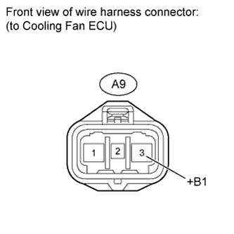
Measure the voltage according to the value(s) in the table below.
Standard voltage Tester Connection Condition Specified Condition A9-3 (+B1) - Body ground Power switch on (IG) 11 to 14 V
NG
INSPECT FUSE (FAN NO. 1 AND E/G RM-IG1-1) Click here
OK 
-
-
CHECK HARNESS AND CONNECTOR (MULTIPLEX NETWORK FRONT LIGHT ECU (FRONT CONTROLLER) - COOLING FAN ECU)
-
Disconnect the multiplex network front light ECU (front controller) connector.
-
Disconnect the cooling fan ECU connector.
-
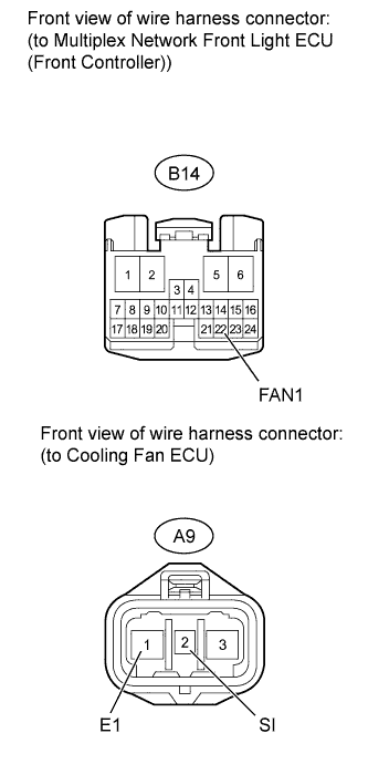
Measure the resistance according to the value(s) in the table below.
Standard resistance Tester Connection Condition Specified Condition B14-22 (FAN1) - A9-2 (SI) Always Below 1 Ω Body ground - A9-1(E1) Always Below 1 Ω B14-22(FAN1) or A9-2(SI) - Body ground Always 10 kΩ or higher
NG 
REPAIR OR REPLACE HARNESS OR CONNECTOR
OK
-
-
INSPECT COOLING FAN MOTOR (COOLING FAN MOTOR AND NO. 2 COOLING FAN MOTOR)
-
Inspect the cooling fan motor Click here.
Result Result Proceed to OK A NG (cooling fan motor) B NG (No. 2 cooling fan motor) C
B
REPLACE COOLING FAN MOTOR Click here
C
REPLACE NO. 2 COOLING FAN MOTOR Click here
A
-
-
INSPECT COOLING FAN ECU
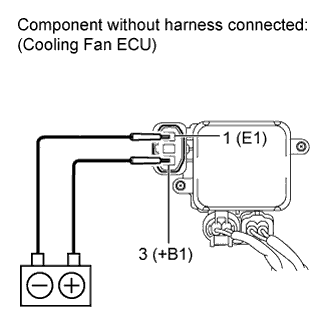
-
Disconnect the cooling fan ECU connectors.
-
Check the cooling fan operation when battery voltage is applied to the terminals of the cooling fan ECU connectors.
OK Cooling fan operates.
NG
REPLACE COOLING FAN ECU Click here
OK
REPLACE MULTIPLEX NETWORK FRONT LIGHT ECU (FRONT CONTROLLER)
-
-
INSPECT FUSE (FAN NO. 1 AND E/G RM-IG1-1)
-
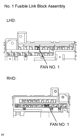
Remove the FAN NO. 1 fuse from the No. 1 fusible link block assembly.
-
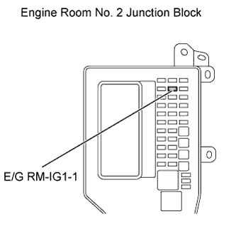
Remove the E/G RM-IG1-1 fuse from the engine room No. 2 junction block.
-
Measure the resistance according to the value(s) in the table below.
Standard resistance Tester Connection Condition Specified Condition FAN NO. 1 fuse Always Below 1 Ω E/G RM-IG1-1 fuse Always Below 1 Ω
NG
CHECK HARNESS AND CONNECTOR (MULTIPLEX NETWORK FRONT LIGHT ECU (FRONT CONTROLLER) - COOLING FAN ECU) Click here
OK
-
-
INSPECT COOLING FAN RELAY (FAN NO. 1)
-
Inspect the cooling fan relay (FAN NO. 1) Click here.
NG
REPLACE COOLING FAN RELAY (FAN NO. 1) Click here
OK
REPAIR OR REPLACE HARNESS OR CONNECTOR (COOLING FAN ECU - BATTERY)
-
-
CHECK HARNESS AND CONNECTOR (MULTIPLEX NETWORK FRONT LIGHT ECU (FRONT CONTROLLER) - COOLING FAN ECU)
-
Disconnect the multiplex network front light ECU (front controller) connector.
-
Disconnect the cooling fan ECU connector.
-
Measure the resistance according to the value(s) in the table below.
Standard resistance Tester Connection Condition Specified Condition B14-22 (FAN1) - A9-2 (SI) Always Below 1 Ω Body ground - A9-1(E1) Always Below 1 Ω B14-22(FAN1) or A9-2(SI) - Body ground Always 10 kΩ or higher
NG
REPAIR OR REPLACE HARNESS OR CONNECTOR
OK
-
-
INSPECT COOLING FAN MOTOR (COOLING FAN MOTOR AND NO. 2 COOLING FAN MOTOR)
-
Inspect the cooling fan motor Click here.
Result Result Proceed to OK A NG (cooling fan motor) B NG (No. 2 cooling fan motor) C
B
REPLACE COOLING FAN MOTOR Click here
C
REPLACE NO. 2 COOLING FAN MOTOR Click here
A
-
-
INSPECT COOLING FAN ECU
-
Disconnect the cooling fan ECU connectors.
-
Check the cooling fan operation when battery voltage is applied to the terminals of the cooling fan ECU connectors.
OK Cooling fan operates.
NG
REPLACE COOLING FAN ECU Click here
OK
REPLACE FUSE
-