SFI SYSTEM, Diagnostic DTC:P0327, P0328, P032C, P032D, P0332, P0333, P033C, P033D

| DTC Code | DTC Name |
|---|---|
| P0327 | Knock Sensor 1 Circuit Low Input (Bank 1 or Single Sensor) |
| P0328 | Knock Sensor 1 Circuit High Input (Bank 1 or Single Sensor) |
| P032C | Knock Sensor 3 Circuit Low |
| P032D | Knock Sensor 3 Circuit High |
| P0332 | Knock Sensor 2 Circuit Low Input (Bank 2) |
| P0333 | Knock Sensor 2 Circuit High Input (Bank 2) |
| P033C | Knock Sensor 4 Circuit Low Input |
| P033D | Knock Sensor 4 Circuit High Input |
DESCRIPTION
A flat type knock sensor (non-resonant type) has a structure that can detect vibrations between approximately 5 kHz and 15 kHz.
The knock sensors are fitted onto the engine block to detect engine knocking.
The knock sensor contains a piezoelectric element which generates a voltage when it becomes deformed.
The voltage is generated when the engine block vibrates due to knocking. Any occurrence of engine knocking can be suppressed by delaying the ignition timing.
| DTC No. | DTC Detection Condition | Trouble Area |
|---|---|---|
| P0327 | Output voltage of knock sensor (for Bank 1 Sensor 1) is 0.5 V or less (1 trip detection logic) |
|
| P0328 | Output voltage of knock sensor (for Bank 1 Sensor 1) is 4.5 V or more (1 trip detection logic) |
|
| P0332 | Output voltage of knock sensor (for Bank 2 Sensor 1) is 0.5 V or less (1 trip detection logic) |
|
| P0333 | Output voltage of knock sensor (for Bank 2 Sensor 1) is 4.5 V or more (1 trip detection logic) |
|
| P032C | Output voltage of knock sensor (for Bank 1 Sensor 2) is 0.5 V or less (1 trip detection logic) |
|
| P032D | Output voltage of knock sensor (for Bank 1 Sensor 2) is 4.5 V or more (1 trip detection logic) |
|
| P033C | Output voltage of knock sensor (for Bank 2 Sensor 2) is 0.5 V or less (1 trip detection logic) |
|
| P033D | Output voltage of knock sensor (for Bank 2 Sensor 2) is 4.5 V or more (1 trip detection logic) |
|
Tech Tips
When DTC P0327, P0328, P0332, P0333, P032C, P032D, P033C or P033D is set, the ECM enters fail-safe mode. During fail-safe mode, the ignition timing is delayed to its maximum retardation. Fail-safe mode continues until the power switch is turned OFF.
Reference: Inspection using an oscilloscope
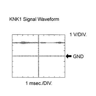
The correct waveform is as shown.
| Item | Content |
|---|---|
| Terminal | KNK1 - EKNK KNK2 - EKN2 KNK3 - EKN3 KNK4 - EKN4 |
| Equipment Setting | 0.01 to 10 V/DIV. 0.01 to 10 msec./DIV. |
| Condition | Keep engine speed at 4000 rpm with warm engine |
MONITOR DESCRIPTION
The knock sensor, located on the cylinder block, detects spark knock. When spark knock occurs, the piezoelectric element of the sensor vibrates. When the ECM detects a voltage in this frequency range, it retards the ignition timing to suppress the spark knock.
The ECM also senses background engine noise with the knock sensor and uses this noise to check for faults in the sensor. If the knock sensor signal level is too low for more than 10 seconds, or if the knock sensor output voltage is outside the normal range, the ECM interprets this as a fault in the knock sensor and sets a DTC.
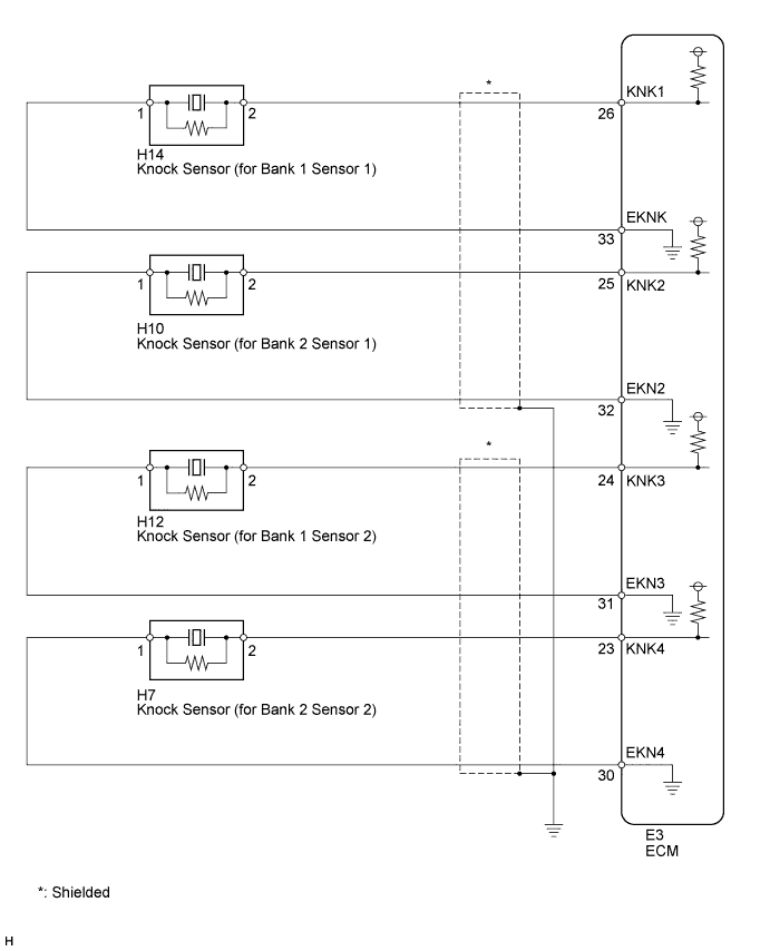
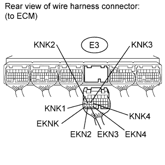
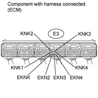
WIRING DIAGRAM
INSPECTION PROCEDURE
Tech Tips
-
DTCs P0327 and P0328 are for the bank 1 sensor 1 knock sensor circuit.
-
DTCs P032C and P032D are for the bank 1 sensor 2 knock sensor circuit.
-
DTCs P0332 and P0333 are for the bank 2 sensor 1 knock sensor circuit.
-
DTCs P033C and P033D are for the bank 2 sensor 2 knock sensor circuit.
-
Read freeze frame data using the intelligent tester. Freeze frame data records the engine condition when malfunctions are detected. When troubleshooting, freeze frame data can help determine if the vehicle was moving or stationary, if the engine was warmed up or not, if the air-fuel ratio was lean or rich, and other data from the time the malfunction occurred.
-
When viewed from the rear of the engine assembly, Bank 1 is on the left side and Bank 2 is on the right side.
PROCEDURE
-
INSPECT KNOCK SENSOR
-
Disconnect the E3 ECM connector.
-
Measure the resistance according to the value(s) in the table below.
Standard resistance Tester Connection Condition Specified Condition E3-26 (KNK1) - E3-33 (EKNK) 20°C (68°F) 120 to 280 kΩ E3-25 (KNK2) - E3-32 (EKN2) 20°C (68°F) 120 to 280 kΩ E3-24 (KNK3) - E3-31 (EKN3) 20°C (68°F) 120 to 280 kΩ E3-23 (KNK4) - E3-30 (EKN4) 20°C (68°F) 120 to 280 kΩ
NG 
CHECK HARNESS AND CONNECTOR (KNOCK SENSOR - ECM) Click here
OK 
-
-
INSPECT ECM
-
Measure the voltage according to the value(s) in the table below.
Standard voltage Tester Connection Switch Condition Specified Condition E3-26 (KNK1) - E3-33 (EKNK) Power switch on (IG) 4.5 to 5.5 V E3-25 (KNK2) - E3-32 (EKN2) Power switch on (IG) 4.5 to 5.5 V E3-24 (KNK3) - E3-31 (EKN3) Power switch on (IG) 4.5 to 5.5 V E3-23 (KNK4) - E3-30 (EKN4) Power switch on (IG) 4.5 to 5.5 V
NG 
REPLACE ECM Click here
OK 
CHECK FOR INTERMITTENT PROBLEMS Click here
-
-
CHECK HARNESS AND CONNECTOR (KNOCK SENSOR - ECM)
-
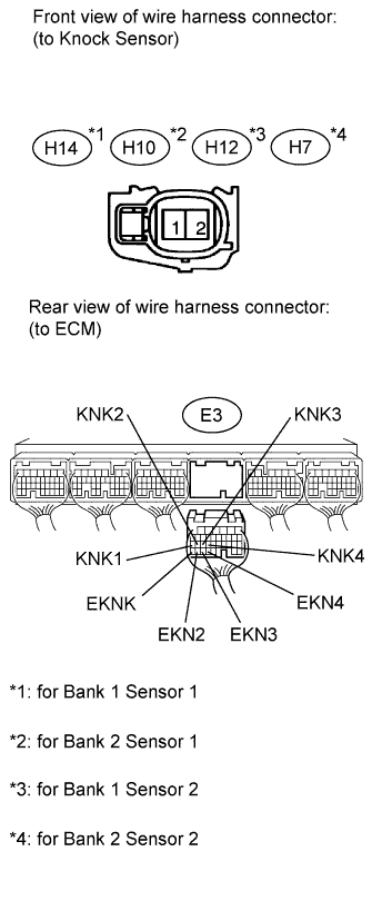
Disconnect the H14, H10, H12 or H7 knock sensor connector.
-
Disconnect the E3 ECM connector.
-
Measure the resistance according to the value(s) in the table below.
Standard resistance (Check for open) Tester Connection Condition Specified Condition H14-2 - E3-26 (KNK1) Always Below 1 Ω H14-1 - E3-33 (EKNK) Always Below 1 Ω H10-2 - E3-25 (KNK2) Always Below 1 Ω H10-1 - E3-32 (EKN2) Always Below 1 Ω H12-2 - E3-24 (KNK3) Always Below 1 Ω H12-1 - E3-31 (EKN3) Always Below 1 Ω H7-2 - E3-23 (KNK4) Always Below 1 Ω H7-1 - E3-30 (EKN4) Always Below 1 Ω Standard resistance (Check for open) Tester Connection Condition Specified Condition H14-2 or E3-26 (KNK1) - Body ground Always 10 kΩ or higher H14-1 or E3-33 (EKNK) - Body ground Always 10 kΩ or higher H10-2 or E3-25 (KNK2) - Body ground Always 10 kΩ or higher H10-1 or E3-32 (EKN2) - Body ground Always 10 kΩ or higher H12-2 or E3-24 (KNK3) - Body ground Always 10 kΩ or higher H12-1 or E3-31 (EKN3) - Body ground Always 10 kΩ or higher H7-2 or E3-23 (KNK4) - Body ground Always 10 kΩ or higher H7-1 or E3-30 (EKN4) - Body ground Always 10 kΩ or higher
NG
REPAIR OR REPLACE HARNESS OR CONNECTOR
OK
REPLACE KNOCK SENSOR Click here
-