SFI SYSTEM, Diagnostic DTC:P1235, P1236

| DTC Code | DTC Name |
|---|---|
| P1235 | High Pressure Fuel Pump Circuit |
| P1236 | High Pressure Fuel Pump No. 2 Circuit |
DESCRIPTION
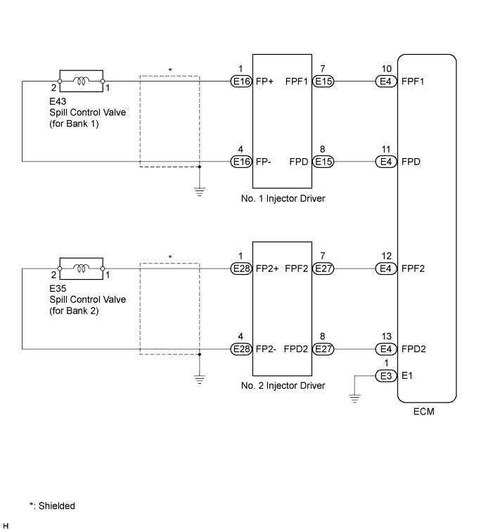
The fuel pump (for high pressure) has a plunger and a spill control valve. The plunger reciprocates by the camshaft rotation and pumps the fuel into the direct fuel injectors. The spill control valve regulates the fuel flow from the fuel tank to the plunger. When the spill control valve opens (ON), the fuel pressure rises. The injector driver operates the spill control valve using DC 50 V. The engine control module (ECM) controls the injector driver to maintain the fuel pressure at 4 to 13 MPa (41 to 133 kgf/cm2, 574 to 1857 psi).
| DTC No. | DTC Detection Condition | Trouble Area |
|---|---|---|
| P1235 | Open or short in fuel pump (for High Pressure of Bank 1) circuit for 1 second or more (1 trip detection logic) |
|
| P1236 | Open or short in fuel pump (for High Pressure of Bank 2) circuit for 1 second or more (1 trip detection logic) |
|
MONITOR DESCRIPTION
The injector driver has the integrated circuit (IC) which monitors the electrical circuit between the spill control valve and injector driver. If an open circuit is detected, the IC sends the malfunction signal (FPD, FPD2) to the ECM. Then, the ECM illuminates the malfunction indicator lamp (MIL) and sets a DTC immediately.
WIRING DIAGRAM
INSPECTION PROCEDURE
Tech Tips
-
Read freeze frame data using the intelligent tester. Freeze frame data records the engine condition when malfunctions are detected. When troubleshooting, freeze frame data can help determine if the vehicle was moving or stationary, if the engine was warmed up or not, if the air-fuel ratio was lean or rich, and other data from the time the malfunction occurred.
-
When viewed from the rear of the engine assembly, Bank 1 is on the left side and Bank 2 is on the right side.
PROCEDURE
-
CHECK DTC
-
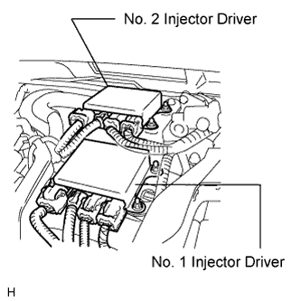
Interchange the No. 1 and No. 2 injector driver Click here.
Note
Do not disconnect and reconnect the connectors with the power switch on (IG), as the injector driver (EDU) may be damaged.
-
Connect the intelligent tester to the DLC3.
-
Turn the power switch on (IG) and turn the tester ON.
-
Clear DTCs Click here.
Note
Before clearing the DTCs, write them down.
-
Turn the power switch on (READY).
-
Enter the following menus: Powertrain / Engine and ECT / DTC.
-
Read the DTC.
Result Display (DTC Output) Proceed to DTCs do not change A DTCs change (change in malfunctioning cylinder or EDU code) B
B 
REPLACE INJECTOR DRIVER Click here
A 
-
-
INSPECT SPILL CONTROL VALVE
-
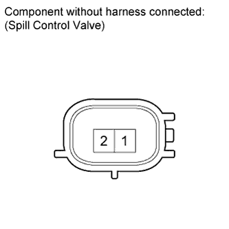
Disconnect the E43 or E35 spill control valve connector.
-
Measure the resistance according to the value(s) in the table below.
Standard resistance Tester Connection Condition Specified Condition 1 - 2 20°C (68°F) 1.19 to 1.39 Ω
NG
REPLACE FUEL PUMP (for High Pressure) Click here
OK
-
-
CHECK HARNESS AND CONNECTOR (INJECTOR DRIVER - SPILL CONTROL VALVE)
-
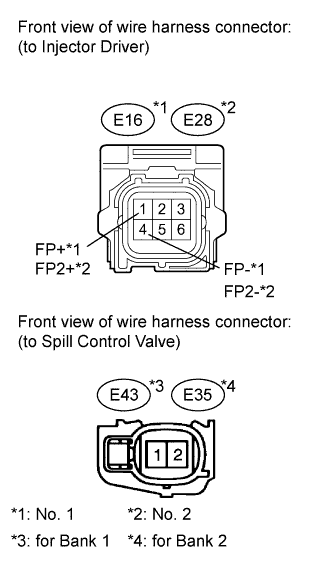
Disconnect the E16 or E28 injector driver (EDU) connector.
-
Disconnect the E43 or E35 spill control valve connector.
-
Measure the resistance according to the value(s) in the table below.
Standard resistance (Check for open) Tester Connection Condition Specified Condition E16-1 (FP+) - E43-1 Always Below 54 mΩ E16-4 (FP-) - E43-2 Always Below 54 mΩ E28-1 (FP2+) - E35-1 Always Below 54 mΩ E28-4 (FP2-) - E35-2 Always Below 54 mΩ Standard resistance (Check for short) Tester Connection Condition Specified Condition E16-1 (FP+) or E43-1 - Engine ground Always 1 MΩ or more E16-4 (FP-) or E43-2 - Engine ground Always 1 MΩ or more E28-1 (FP2+) or E35-1 - Engine ground Always 1 MΩ or more E28-4 (FP2-) or E35-2 - Engine ground Always 1 MΩ or more
NG
REPAIR OR REPLACE HARNESS OR CONNECTOR
OK
-
-
CHECK HARNESS AND CONNECTOR (INJECTOR DRIVER - ECM)
-
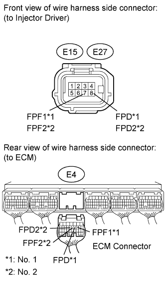
Disconnect the E15 or E27 injector driver connector.
-
Disconnect the E4 ECM connector.
-
Measure the resistance according to the value(s) in the table below.
Standard resistance (Check for open) Tester Connection Condition Specified Condition E15-8 (FPD) - E4-11 (FPD) Always Below 1 Ω E15-7 (FPF1) - E4-10 (FPF1) Always Below 1 Ω E27-8 (FPD2) - E4-13 (FPD2) Always Below 1 Ω E27-7 (FPF2) - E4-12 (FPF2) Always Below 1 Ω Standard resistance (Check for short) Tester Connection Condition Specified Condition E15-8 (FPD) or E4-11 (FPD) - Body ground Always 10 kΩ or higher E15-7 (FPF1) or E4-10 (FPF1) - Body ground Always 10 kΩ or higher E27-8 (FPD2) or E4-13 (FPD2) - Body ground Always 10 kΩ or higher E27-7 (FPF2) or E4-12 (FPF2) - Body ground Always 10 kΩ or higher
NG
REPAIR OR REPLACE HARNESS OR CONNECTOR
OK 
REPLACE ECM Click here
-