SFI SYSTEM, Diagnostic DTC:P0102, P0103, P010C, P010D

| DTC Code | DTC Name |
|---|---|
| P0102 | Mass Air Flow Circuit Low |
| P0103 | Mass Air Flow Circuit High |
| P010C | Mass or Volume Air Flow "A" Circuit Low Input |
| P010D | Mass or Volume Air Flow "A" Circuit High Input |
DESCRIPTION
The Mass Air Flow (MAF) meter is a sensor that measures the amount of air flowing through the valve.
The ECM uses this information to determine the fuel injection time and to provide an appropriate air-fuel ratio.
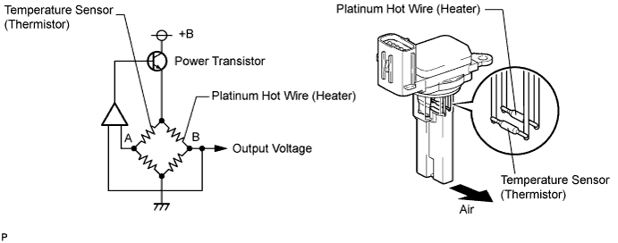
Inside the MAF meter, there is a heated platinum wire which is exposed to the flow of intake air.
By applying a specific electrical current to the wire, the ECM heats it to a given temperature. The flow of incoming air cools both the wire and an internal thermistor, affecting their resistance. To maintain a constant current value, the ECM varies the voltage applied to these components in the MAF meter. The voltage level is proportional to the airflow through the sensor, and the ECM uses it to calculate the intake air volume.
The circuit is constructed so that the platinum hot wire and the temperature sensor provide a bridge circuit, and the power transistor is controlled so that the potentials of A and B remain equal to maintain the predetermined temperature.
Tech Tips
When any of these DTCs are set, the ECM enters fail-safe mode. During fail-safe mode, the ignition timing is calculated by the ECM, according to the engine RPM and throttle valve position. Fail-safe mode continues until a pass condition is detected.
| DTC No. | DTC Detection Condition | Trouble Area |
|---|---|---|
| P0102 P010C |
Open in Mass Air Flow (MAF) meter (for Bank 1, 2) circuit for 3 seconds (1 trip detection logic) |
|
| P0103 P010D |
Short in Mass Air Flow (MAF) meter (for Bank 1, 2) circuit for 3 seconds (1 trip detection logic) |
|
Tech Tips
When any of these DTCs are set, check the air-flow rate by entering the following menus: Powertrain / Engine and ECT / Data List / All Data / MAF Sensor 1 or MAF Sensor 2.
| Mass Air Flow Rate (gm/sec.) | Malfunction |
|---|---|
| Approximately 0.0 |
|
| 160.0 or more |
|
MONITOR DESCRIPTION
If there is a defect in the MAF meter or an open or short circuit, the voltage level deviates from the normal operating range. The ECM interprets this deviation as a malfunction in the MAF meter and sets a DTC.
Example:
When the sensor output voltage remains less than 0.2 V, or more than 4.9 V, for more than 3 seconds, the ECM sets a DTC.
If the malfunction is not repaired successfully, a DTC is set 3 seconds after the engine is next started.
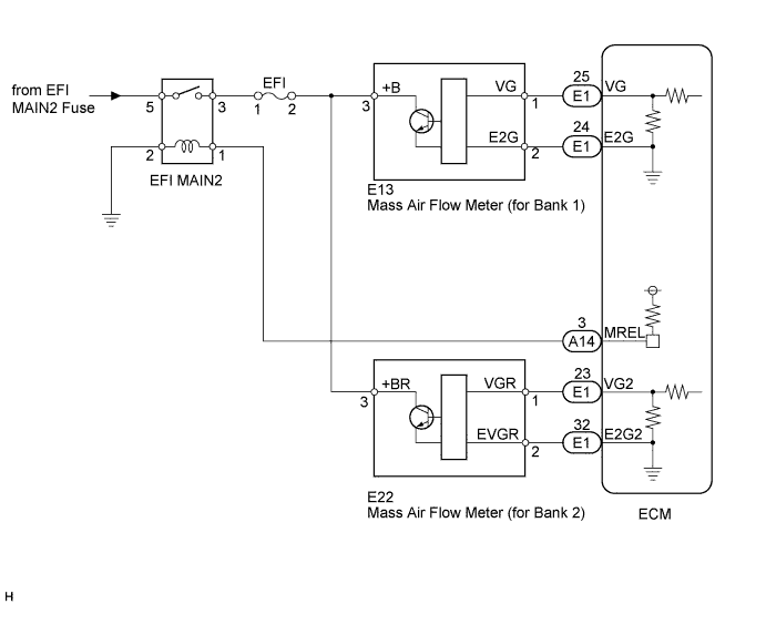
WIRING DIAGRAM
INSPECTION PROCEDURE
Tech Tips
-
Read freeze frame data using the GTS. Freeze frame data records the engine condition when malfunctions are detected. When troubleshooting, freeze frame data can help determine if the vehicle was moving or stationary, if the engine was warmed up or not, if the air-fuel ratio was lean or rich, and other data from the time the malfunction occurred.
-
When viewed from the rear of the engine assembly, Bank 1 is on the left side and Bank 2 is on the right side.
PROCEDURE
-
READ DTC OUTPUT
-
Connect the GTS to the DLC3.
-
Turn the power switch on (IG).
-
Turn the GTS on.
-
Enter the following menus: Powertrain / Engine and ECT / Trouble Codes.
-
Read the DTCs.
Result Result Proceed to DTC P0102 is output A DTC P0103 is output B
B 
INSPECT ECM (SENSOR GROUND) Click here
A 
-
-
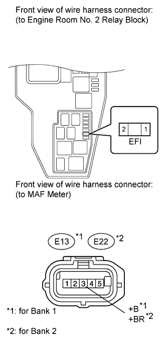
INSPECT MASS AIR FLOW METER (POWER SOURCE VOLTAGE)
-
Disconnect the E13 or E22 MAF meter connector.
-
Measure the voltage according to the value(s) in the table below.
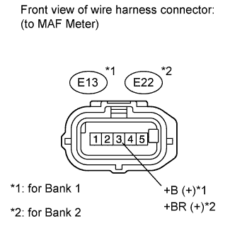
Standard voltage Tester Connection Switch Condition Specified Condition E13-3 (+B) - Body ground Power switch on (IG) 11 to 14 V E22-3 (+BR) - Body ground Power switch on (IG) 11 to 14 V
NG
CHECK HARNESS AND CONNECTOR (MASS AIR FLOW METER - EFI FUSE) Click here
OK
-
-
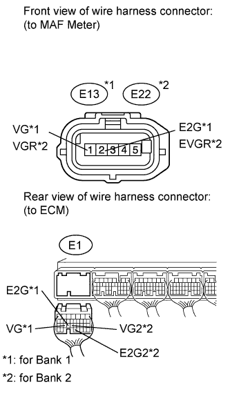
INSPECT ECM (VG VOLTAGE)
-
Put the engine in inspection mode Click here.
-
Measure the voltage according to the value(s) in the table below.
Tech Tips
The shift lever should be in the P or N position and the A/C switch should be turned OFF.
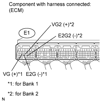
Standard voltage Tester Connection Condition Specified Condition E1-25 (VG) - E1-24 (E2G) Engine idling 0.5 to 3.0 V E1-23 (VG2) - E1-32 (E2G2) Engine idling 0.5 to 3.0 V
NG
CHECK HARNESS AND CONNECTOR (MASS AIR FLOW METER - ECM) Click here
OK 
REPLACE ECM Click here
-
-
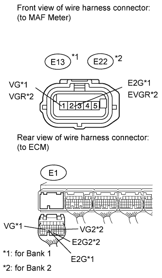
CHECK HARNESS AND CONNECTOR (MASS AIR FLOW METER - ECM)
-
Disconnect the E13 or E22 MAF meter connector.
-
Disconnect the E1 ECM connector.
-
Measure the resistance according to the value(s) in the table below.
Standard resistance (Check for open) Tester Connection Condition Specified Condition E13-1 (VG) - E1-25 (VG) Always Below 1 Ω E13-2 (E2G) - E1-24 (E2G) Always Below 1 Ω E22-1 (VGR) - E1-23 (VG2) Always Below 1 Ω E22-2 (EVGR) - E1-32 (E2G2) Always Below 1 Ω Standard resistance (Check for short) Tester Connection Condition Specified Condition E13-1 (VG) or E1-25 (VG) - Body ground Always 10 kΩ or higher E22-1 (VGR) or E1-23 (VG2) - Body ground Always 10 kΩ or higher
NG 
REPAIR OR REPLACE HARNESS OR CONNECTOR
OK
REPLACE MASS AIR FLOW METER (for Bank 1 or Bank 2) Click here
-
-
CHECK HARNESS AND CONNECTOR (MASS AIR FLOW METER - EFI FUSE)
-
Remove the EFI fuse from the engine room No. 2 relay block.
-
Disconnect the E13 or E22 MAF meter connector.
-
Measure the resistance according to the value(s) in the table below.
Standard resistance (Check for open) Tester Connection Condition Specified Condition EFI fuse (2) - E13-3 (+B) Always Below 1 Ω EFI fuse (2) - E22-3 (+BR) Always Below 1 Ω Standard resistance (Check for short) Tester Connection Condition Specified Condition EFI fuse (2) or E13-3 (+B) - Body ground Always 10 kΩ or higher EFI fuse (2) or E22-3 (+BR) - Body ground Always 10 kΩ or higher
NG
REPAIR OR REPLACE HARNESS OR CONNECTOR
OK
CHECK ECM POWER SOURCE CIRCUIT Click here
-
-
INSPECT ECM (SENSOR GROUND)
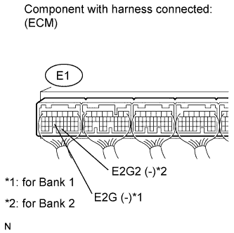
-
Measure the resistance according to the value(s) in the table below.
Standard resistance Tester Connection Condition Specified Condition E1-24 (E2G) - Body ground Always Below 1 Ω E1-32 (E2G2) - Body ground Always Below 1 Ω
NG
REPLACE ECM Click here
OK
-
-
CHECK HARNESS AND CONNECTOR (MASS AIR FLOW METER - ECM)
-
Disconnect the E13 or E22 MAF meter connector.
-
Disconnect the E1 ECM connector.
-
Measure the resistance according to the value(s) in the table below.
Standard resistance (Check for open) Tester Connection Condition Specified Condition E13-1 (VG) - E1-25 (VG) Always Below 1 Ω E13-2 (E2G) - E1-24 (E2G) Always Below 1 Ω E22-1 (VGR) - E1-23 (VG2) Always Below 1 Ω E22-2 (EVGR) - E1-32 (E2G2) Always Below 1 Ω Standard resistance (Check for short) Tester Connection Condition Specified Condition E13-1 (VG) or E1-25 (VG) - Body ground Always 10 kΩ or higher E22-1 (VGR) or E1-23 (VG2) - Body ground Always 10 kΩ or higher
NG
REPAIR OR REPLACE HARNESS OR CONNECTOR
OK
REPLACE MASS AIR FLOW METER (for Bank 1 or Bank 2) Click here
-