SFI SYSTEM, Diagnostic DTC:P0087

| DTC Code | DTC Name |
|---|---|
| P0087 | Fuel Rail / System Pressure - Too Low |
DESCRIPTION
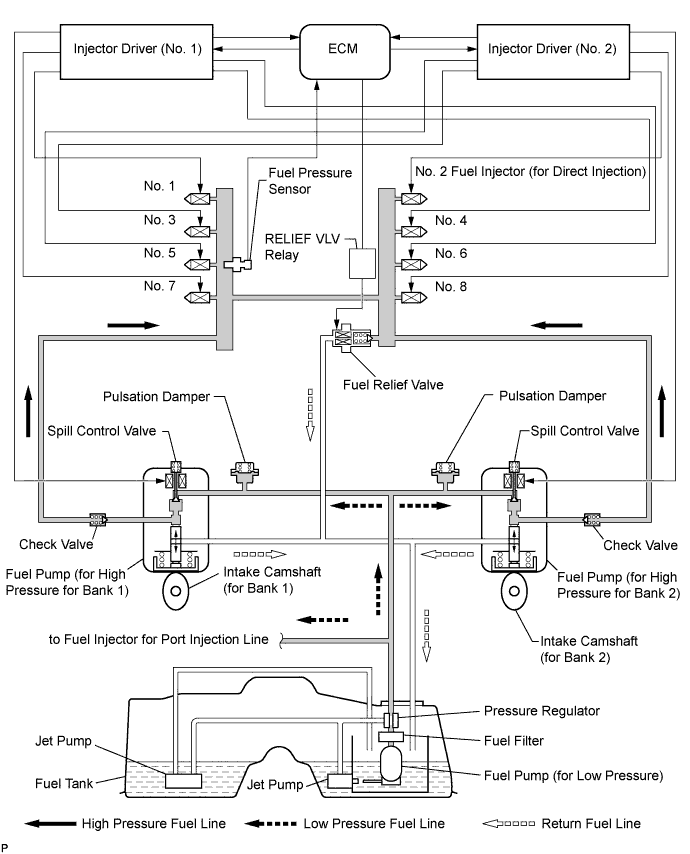
The D-4S (Direct injection 4-stroke gasoline engine Superior) has two fuel injection systems. One is the port fuel injection system. The other is the direct fuel injection system. The direct fuel injection system has three functions:
-
In the regulating function, the fuel pump (for high pressure) builds up and regulates the fuel pressure. The fuel pump (for high pressure) has a plunger and a spill control valve. The plunger reciprocates by the camshaft rotation and pumps the fuel into the direct fuel injectors. The spill control valve regulates the fuel flow from the fuel tank to the plunger. When the spill control valve opens (ON), the fuel pressure rises. The injector driver operates the spill control valve using DC 50 V. The engine control module (ECM) controls the injector driver to maintain the fuel pressure at 4 to 13 MPa (41 to 133 kg/cm2, 574 to 1857 psi).
-
In the limiting function, the fuel relief valve mechanically opens to release the fuel pressure when the fuel pressure exceeds 15.3 MPa (156 kgf/cm2, 2185 psi).
-
In the releasing function, the ECM opens the fuel relief valve for a few seconds to release the fuel pressure immediately after the power switch is turned OFF. This prevents fuel leaks from the direct injector while the engine is stopped.
| DTC No. | DTC Detection Condition | Trouble Area |
|---|---|---|
| P0087 | Even though ECM commands fuel pump for high pressure to open spill control valve, fuel pressure decreases 5 MPa (51.0 kgf/cm2, 725 psi) from target pressure for more than 10 seconds (1 trip detection logic) |
|
MONITOR DESCRIPTION
To monitor fuel pressure drops in the direct fuel injection, the ECM measures the fuel pressure using the fuel pressure sensor. If the sensor value is lower than the target fuel pressure value, the ECM interprets this as a malfunction. The ECM illuminates the malfunction indicator lamp (MIL) and sets the diagnosis trouble code (DTC) immediately.
INSPECTION PROCEDURE
Tech Tips
-
Read freeze frame data using the intelligent tester. Freeze frame data records the engine condition when malfunctions are detected. When troubleshooting, freeze frame data can help determine if the vehicle was moving or stationary, if the engine was warmed up or not, if the air-fuel ratio was lean or rich, and other data from the time the malfunction occurred.
-
When viewed from the rear of the engine assembly, Bank 1 is on the left side and Bank 2 is on the right side.
PROCEDURE
-
CHECK FUEL LEAK
-
Check around and beneath the car for gasoline leaks, fumes, etc.
OK No gasoline leaks present.
NG 
REPAIR OR REPLACE FUEL LEAK POINT
OK 
-
-
CHECK OTHER DTCS OUTPUT (IN ADDITION TO DTC P0087)
-
Connect the intelligent tester to the DLC3.
-
Turn the power switch on (IG) and turn the tester ON.
-
Enter the following menus: Powertrain / Engine and ECT / DTC.
-
Read the DTCs.
Result Display (DTC output) Proceed to P0087 A P0087 and other DTCs B
B
GO TO DTC CHART Click here
A
-
-
CHECK MISFIRE COUNT
-
Put the engine in inspection mode Click here.
-
Connect the intelligent tester to the DLC3.
-
Turn the tester ON.
-
Enter the following menus: Powertrain / Engine and ECT / Active Test / Control the Injection Way / Direct.
-
Allow the engine to idle.
-
Monitor all of the misfire count values that are displayed on the tester: Powertrain / Engine and ECT / Data List / Misfire / Cylinder #1 Misfire count to Cylinder #8 Misfire count.
If no misfire counts occur for any of the cylinders, perform the following procedure:
-
Move the shift lever to the D position.
-
Monitor all of the misfire count values that are displayed on the tester.
Result Misfire Count Proceed to No misfire counts, or misfire counts occur randomly in all cylinders A Misfire counts occur in particular cylinder B
-
B
REPLACE FUEL INJECTOR (for Direct Injection) Click here
A
-
-
INSPECT FUEL PRESSURE (LOW PRESSURE)
-
Inspect the fuel pressure Click here.
NG
REPAIR OR REPLACE FUEL SYSTEM Click here
OK
-
-
INSPECT INJECTOR DRIVER (No. 1 and No. 2)
-
Turn the power switch off.
-
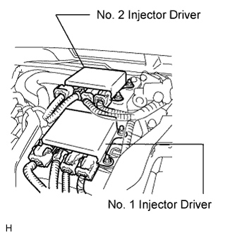
Replace the No. 1 and No. 2 injector drivers with new or normally functioning ones.
Note
Do not disconnect and reconnect the connectors with the power switch on (IG), as the injector driver (EDU) may be damaged.
-
Turn the power switch on (READY).
-
Clear DTCs Click here.
-
Perform the driving test.
-
Enter the following menus: Powertrain / Engine and ECT / DTC.
-
Read the DTCs.
Result Display (DTC Output) Proceed to P0087 A No output B
B
REPLACE INJECTOR DRIVER (No. 1 and No. 2) Click here
A
-
-
REPLACE FUEL PUMP (for High Pressure of Bank 1 and Bank 2)
-
Replace the fuel pump (for High Pressure of Bank 1 and Bank 2) Click here.
NEXT
-
-
CHECK IF DTC OUTPUT REOCCURS
-
Connect the intelligent tester to the DLC3.
-
Turn the power switch on (IG).
-
Turn the tester ON.
-
Clear DTCs Click here.
-
Perform the driving test.
-
Enter the following menus: Powertrain / Engine and ECT / DTC.
-
Read DTCs.
Result Display (DTC Output) Proceed to P0087 A No output B
B
END
A 
REPLACE ECM Click here
-