ENGINE GENERAL MAINTENANCE
Tech Tips
Inspect these items on a cooled down engine.
-
INSPECT DRIVE BELT
-
Check the belt for wear, cracks or other signs of damage.
If any of the following defects is found, replace the V-ribbed belt.
-
The belt is cracked.
-
The belt is worn out to the extent that the cords are exposed.
-
The belt has chunks missing from the ribs.
-
-
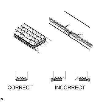
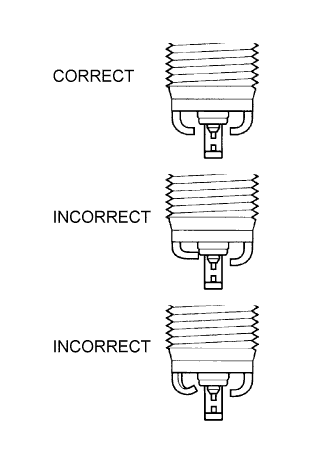
Check that the belt fits properly in the ribbed grooves.
Tech Tips
Check with your hand to confirm that the belt has not slipped out of the grooves on the bottom of the pulley. If it has slipped out, replace the V-ribbed belt. Install a new V-ribbed belt correctly.
-
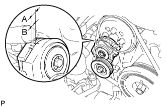
Check that the alignment mark on the belt tensioner is within area "A".
If it is outside area "A", replace the V-ribbed belt.
Tech Tips
When a new belt is installed, the alignment mark should be within area "B". If not, the V-ribbed belt is not installed correctly.
-
-
REPLACE ENGINE OIL AND OIL FILTER
-
Replace the engine oil and oil filter Click here.
-
-
INSPECT COOLING AND HEATER SYSTEM
-
Check that the radiator, condenser and/or intercooler are not blocked with leaves, dirt or insects, and clean them if necessary. Also check the hose for loose connections, corrosion, etc.
-
-
INSPECT ENGINE COOLANT
-
Inspect the engine coolant Click here.
-
-
REPLACE ENGINE COOLANT
-
Replace the engine coolant Click here.
-
-
INSPECT INVERTER COOLANT
-
Inspect the inverter coolant Click here.
-
-
REPLACE INVERTER COOLANT
-
Replace the inverter coolant Click here.
-
-
INSPECT EXHAUST PIPES AND MOUNTINGS
-
Visually check the pipes, hangers and connections for severe corrosion, leaks or damage.
-
-
REPLACE SPARK PLUGS
Note
Do not use a wire brush for cleaning.
-
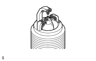
Check the electrode.
-
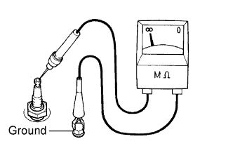
Using a megohmmeter, measure the insulation resistance.
Standard insulation resistance Tester Connection Condition Specified Condition Spark Plug (terminal part) - Body Ground Always 10 MΩ or higher If a megohmmeter is not available, perform the following simple inspection instead.
-
-
Alternative inspection method:
-
Set the vehicle to inspection mode Click here.
-
Quickly accelerate the engine to 2500 rpm 5 times.*
Note
*: Do not perform this step if P0300 (misfire detection) or a related DTC is stored.
-
Remove the spark plug.
-
Visually check the spark plug.
If the electrode is dry, the spark plug is functioning properly. If the electrode is damp, proceed to the next step.
-
-
Check the spark plug for any damage to its threads and insulator.
If there is any damage, replace the spark plug. If not, reinstall the spark plug.
Recommended spark plug Manufacturer Product DENSO made FK20HBR11 Tech Tips
Maximum electrode gap for a used spark plug: 1.4 mm (0.0551 in.)
If the gap is greater than the maximum, replace the spark plug.
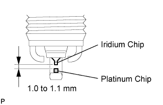
Electrode gap for a new spark plug: 1.0 to 1.1 mm (0.0394 to 0.0433 in.)
Note
Do not adjust the electrode gap of any spark plug, as the ground electrode tip will be damaged.
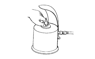
If the electrode has traces of wet carbon, allow it to dry and then clean it with a spark plug cleaner.
Standard air pressure 588 kPa (6.0 kgf/cm2, 85 psi) Standard duration 20 seconds or less Tech Tips
Only use the spark plug cleaner when the electrode is free of oil. If the electrode has traces of oil, use gasoline to clean off the oil before using the spark plug cleaner.
-
-
INSPECT AUXILIARY BATTERY
Note
If the auxiliary battery is fully depleted or "READY" does not light up, recharge the auxiliary battery. Check the auxiliary battery again before the vehicle is returned to the customer.
-
Check the auxiliary battery for damage or deformation.
If there is damage, deformation or leakage, replace the auxiliary battery.
-
Eliminate any surface charge.
-
Drive the vehicle, and stop the engine.
-
Within 20 seconds after the engine is stopped, turn the power switch ON, and turn on electrical systems (the headlights, blower motor and rear window defogger, etc.).
-
-
Turn the power switch OFF, and turn off the electrical systems.
-
Wait 20 minutes, and then measure the auxiliary battery voltage.
-
Measure the voltage according to the value(s) in the table below.
Standard voltage Tester Connection Condition Specified Condition Positive (+) terminal - Negative (-) terminal 20°C (68°F) 12.5 to 12.9 V Tech Tips
If the voltage is not as specified, charge the auxiliary battery.
-
-
-
REPLACE FUEL FILTER
-
Replace the fuel filter Click here.
-
-
ADD FUEL INJECTION SYSTEM
-
Add fuel injector cleaner to the fuel tank (Refer to the Service Bulletin for the fuel injection cleaner).
-
-
INSPECT AIR CLEANER FILTER
-
Remove the air cleaner filter.
-
Visually check that the air cleaner filter is not excessively damaged or oily.
-
Replace the air cleaner filter with a new one, if necessary.
-
-
INSPECT FUEL LINES, FUEL LINE CONNECTIONS, FUEL TANK VAPOR VENT SYSTEM HOSES AND FUEL TANK BAND
-
Visually check the fuel lines and hoses for cracks, leakage, loose connections and deformation. Also, visually check the tank band for looseness.
-
-
INSPECT FUEL TANK CAP ASSEMBLY
-
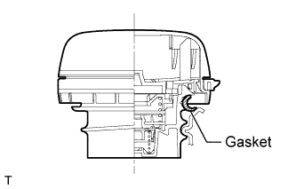
Visually check if the cap and gasket are deformed or damaged.
If necessary, replace the fuel tank cap assembly.
-
-
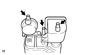
INSPECT CHARCOAL CANISTER
-
Visually check the canister for cracks or damage.
If cracks or damage are found, replace the canister.
-
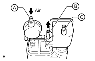
Blow 4 kPa (40.7 gf/cm2, 0.6 psi) of compressed air into port A and check that air flows without resistance from port B and port C.
If the result is not as specified, replace the canister.
-
Apply a vacuum of 2 kPa (15 mmHg, 0.591 in.Hg) to port A. Check that the vacuum does not decrease when ports B and C are closed, and check that the vacuum does not decrease when port B is released.
If the result is not as specified, replace the canister.
-