KNOCK SENSOR REMOVAL

Tech Tips
When viewed from the rear of the engine assembly, Bank 1 is on the left side and Bank 2 is on the right side.
-
REMOVE INTAKE MANIFOLD
-
REMOVE NO. 1 ENGINE COVER SUB-ASSEMBLY
-
REMOVE NO. 2 ENGINE COVER SUB-ASSEMBLY
-
REMOVE NO. 2 ENGINE COVER SUB-ASSEMBLY LH
-
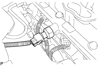
REMOVE NO. 4 FUEL PIPE SUB-ASSEMBLY
-
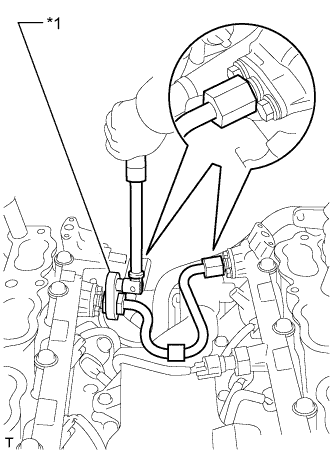
Text in Illustration *1 Union Nut Wrench Using a 19 mm union nut wrench, remove the No. 4 fuel pipe sub-assembly.
-
-
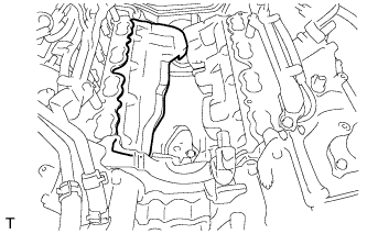
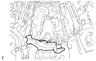
REMOVE SEPARATOR CASE
-
Disconnect the fuel pressure sensor connector.
-
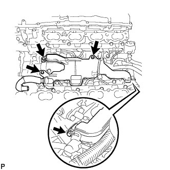
Remove the 4 bolts and separator case.
-
-
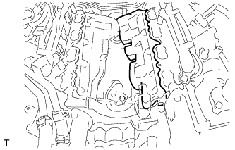
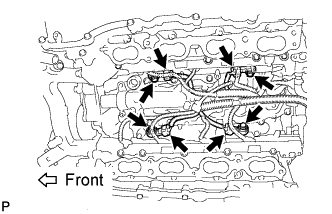
REMOVE KNOCK SENSOR
-
Disconnect the 4 knock sensor connectors.
-
Remove the 4 bolts and 4 knock sensors.
-