VVT SENSOR REMOVAL

Tech Tips
When viewed from the rear of the engine assembly, Bank 1 is on the left side and Bank 2 is on the right side.
-
REMOVE V-BANK COVER SUB-ASSEMBLY
-

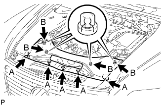
While using both hands, lift the rear side of the V-bank cover sub-assembly upwards to detach the 4 clips labeled B. Slide the V-bank cover sub-assembly towards the front of the vehicle to detach the 2 clips labeled A, and remove the V-bank cover sub-assembly.
Note
The V-bank cover sub-assembly may be damaged if its front and rear are lifted at the same time.
-
-
REMOVE AIR CLEANER INLET COVER SUB-ASSEMBLY
-
Remove the 5 clips labeled A.
-
Lift up the air cleaner inlet cover sub-assembly to detach the 4 clips labeled B, and remove the air cleaner inlet cover sub-assembly.
-
-
REMOVE NO. 1 AIR CLEANER INLET
-
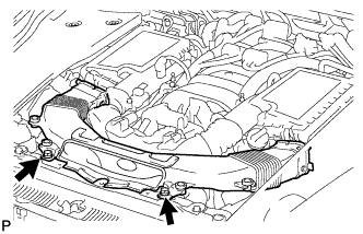
Remove the 2 bolts.
-
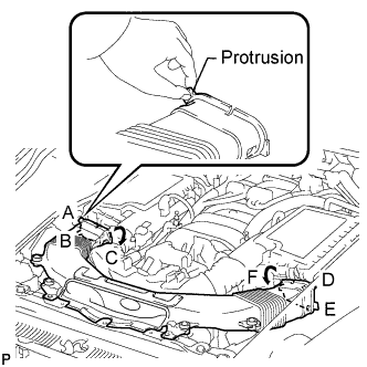
Hold the No. 1 air cleaner inlet by the protrusions labeled A and B, and detach the connections.
-
Rotate the No. 1 air cleaner inlet as shown in the illustration to detach the protrusion labeled C.
-
Hold the No. 1 air cleaner inlet by the protrusions labeled D and E, and detach the connections.
-
Rotate the No. 1 air cleaner inlet as shown in the illustration to detach the protrusion labeled F.
-
-
REMOVE AIR CLEANER ASSEMBLY LH
-
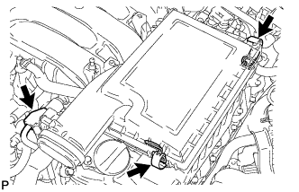
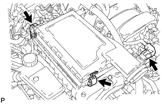
Disconnect the mass air flow meter connector.
-
Release the 2 clamps and remove the air cleaner cap LH.
-
Remove the air cleaner filter element from the air cleaner case LH.
-
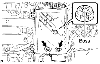
Remove the 2 nuts and detach the air cleaner case LH from the boss.
-
-
REMOVE AIR CLEANER ASSEMBLY RH
-
Disconnect the mass air flow meter connector.
-
Release the 2 clamps and remove the air cleaner cap RH.
-
Remove the air cleaner filter element from the air cleaner case RH.
-
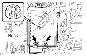
Remove the 2 nuts and detach the air cleaner case RH from the boss.
-
-
REMOVE VVT SENSOR
-
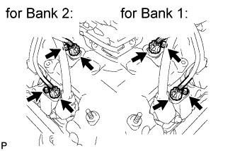
Disconnect the 4 VVT sensor connectors.
-
Remove the 4 bolts and 4 VVT sensors.
-