THROTTLE BODY INSTALLATION

-
INSTALL THROTTLE BODY ASSEMBLY
-
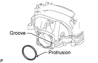
Install a new gasket to the intake manifold.
Tech Tips
Align the protrusion of the gasket with the groove on the intake manifold.
-
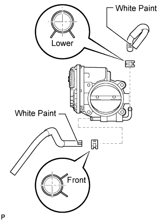
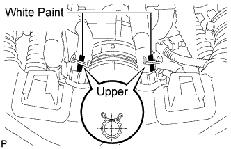
Connect the No. 4 water and No. 5 water by-pass hoses to the throttle body assembly.
Tech Tips
-
Position the claws of the clamps as shown in the illustration.
-
Install the clamps so that they are within the hose's paint marks.
-
-
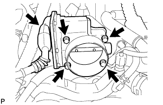
Install the throttle body assembly with the 4 bolts.
- Torque:
- 10 N*m { 102 kgf*cm, 7 ft.*lbf }
-
Connect the throttle body motor connector.
-
-
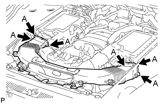
INSTALL INTAKE AIR CONNECTOR PIPE
-
Align the protrusion of the intake air resonator with the cutout of the bracket and insert the protrusion.
-
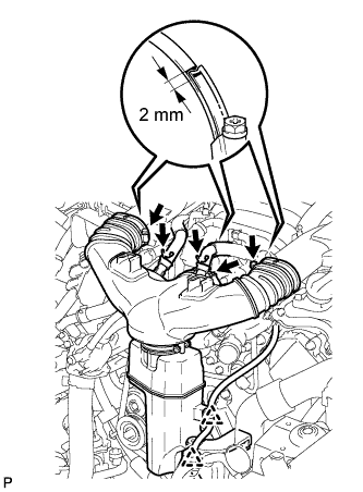
Install the intake air connector pipe with the 3 hose clamps.
- Torque:
- for intake air connector pipe and throttle body
- 4.8 N*m { 49 kgf*cm, 42 in.*lbf }
- for intake air connector pipe and intake air resonator
- 3.8 N*m { 39 kgf*cm, 34 in.*lbf }
Note
Insert the protrusion of the intake air connector pipe into the hole of the hose clamp.
Tech Tips
-
The intake air connector pipe and throttle body clamp can be tightened within the range of 4.0 N*m (41 kgf*cm, 35 in.*lbf) to 5.5 N*m (56 kgf*cm, 49 in.*lbf), and the intake air connector pipe and intake air resonator clamp can be tightened within the range of 2.0 N*m (20 kgf*cm, 18 in.*lbf) to 5.5 N*m (56 kgf*cm, 49 in.*lbf).
-
When tightening the hose clamp, make sure the hose clamp's end is within the painted white line (width: 2 mm (0.0787 in.)).
-
Attach the 2 wire harness clamps.
-
Connect the No. 1 ventilation hose and No. 2 ventilation hose to the intake air connector pipe.
Tech Tips
-
Position the claws of the clamps as shown in the illustration.
-
Install the clamps so that they are within the hose's paint marks.
-
-
-
INSTALL NO. 1 AIR CLEANER INLET
-
Align the holes with the connection areas labeled A, and attach the No. 1 air cleaner inlet.
-
Install the No. 1 air cleaner inlet with the 2 bolts.
- Torque:
- 5.0 N*m { 51 kgf*cm, 44 in.*lbf }
-
-
ADD ENGINE COOLANT
CAUTION:
Do not remove the radiator reservoir cap while the engine and radiator are still hot. Pressurized, hot coolant and steam may be released and cause serious burns.
Tech Tips
Before adding coolant, turn the A/C switch off.
Total capacity 11.1 liters (11.7 US qts, 9.8 Imp. qts)
-
Tighten the radiator drain cock plug.
-
Tighten the 2 cylinder block drain cock plugs.
- Torque:
- 13 N*m { 133 kgf*cm, 10 ft.*lbf }
-
Add TOYOTA Super Long Life Coolant (SLLC) into the radiator reservoir.
Capacity 5.0 liters (5.3 US qts, 4.4 Imp. qts) Tech Tips
TOYOTA vehicles are filled with TOYOTA SLLC at the factory. In order to avoid damage to the engine cooling system and other technical problems, only use TOYOTA SLLC or similar high quality ethylene glycol based non-silicate, non-amine, non-nitrite, non-borate coolant with long-life hybrid organic acid technology (coolant with long-life hybrid organic acid technology consists of a combination of low phosphates and organic acids).
-
Further add coolant into the reservoir until it reaches the FULL line.
-
Press the No. 1 and No. 2 radiator hoses several times by hand, and then check the coolant level.
If the coolant level is low, add coolant.
-
Using a 6 mm hexagon wrench, install the vent plug.
- Torque:
- 1.5 N*m { 15 kgf*cm, 13 in.*lbf }
-
Bleed air from the cooling system.
Tech Tips
Before starting the engine to warm up the engine, turn the A/C switch off.
-
Put the engine in inspection mode Click here.
-
While idling the engine for approximately 10 minutes, make sure the coolant remains at the FULL line by adding coolant as necessary.
-
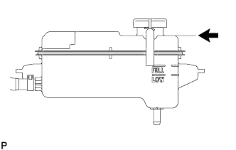
After idling the engine for 10 minutes, add coolant until it reaches the B line.
Capacity 2.5 to 3.5 liters (2.6 to 3.7 US qts, 2.2 to 3.1 Imp. qts) Text in Illustration 
B Line Tech Tips
The B line is the lower edge of the inner wall of the filler neck.
-
Close the radiator reservoir cap, and run the engine at 1500 to 2000 rpm for 5 minutes.
CAUTION:
-
Wear protective gloves.
-
Be careful as the radiator hose is hot.
-
Keep your hands away from the radiator fan.
Tech Tips
The thermostat open timing can be confirmed by pressing the No. 1 radiator hose by hand, and checking when the SLLC starts to flow inside the hose.
-
-
-
Stop the engine and wait until the coolant cools down to ambient temperature.
-
Check the coolant level.
If the coolant level is below the FULL line, add coolant until it reaches the FULL line.
-
-
INSPECT FOR COOLANT LEAK
CAUTION:
Do not remove the radiator reservoir cap while the engine and radiator are still hot. Pressurized, hot engine coolant and steam may be released and cause serious burns.
Note
Before each inspection, turn the A/C switch OFF.
-
Fill the radiator with coolant and attach a radiator cap tester.
-
Warm up the engine.
-
Using the radiator cap tester, increase the pressure inside the radiator to 118 kPa (1.2 kgf/cm2, 17 psi), and check that the pressure does not drop.
If the pressure drops, check the hoses, radiator and engine water pump for leaks. If no external leaks are found, check the heater core, cylinder block and head.
-
-
INSTALL AIR CLEANER INLET COVER SUB-ASSEMBLY
-
Attach the 4 clips labeled B.
Note
-
Make sure the clips are attached securely.
-
Attaching the clips forcefully or hitting the top of the clips may damage them.
-
-
Install the air cleaner inlet cover sub-assembly with the 5 clips labeled A.
-
-
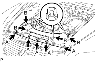
INSTALL V-BANK COVER SUB-ASSEMBLY
-

After sliding the V-bank cover sub-assembly from the vehicle front to the rear to attach the 2 clips labeled A, attach the 4 clips labeled B and install the V-bank cover sub-assembly.
CAUTION:
-
Make sure the clips are attached securely.
-
Attaching the clips forcefully or hitting the top of the clips may damage them.
-
-
-
INSTALL NO. 1 ENGINE UNDER COVER
-
Install the No. 1 engine under cover with the 13 screws and 7 clips.
-
-
INSTALL FRONT WHEEL OPENING EXTENSION PAD LH
-
Install the front wheel opening extension pad LH with the 5 screws.
-
-
INSTALL FRONT WHEEL OPENING EXTENSION PAD RH
Tech Tips
Use the same procedure described for the LH side.
-
PERFORM INITIALIZATION
Note
-
Be sure to perform this procedure after reassembling the throttle body assembly or removing and reinstalling any throttle body component.
-
Perform the following procedure after replacing the ECM, throttle body assembly or any throttle body components. The following procedure should also be performed if the throttle body is cleaned.
-
Be sure to perform this procedure after reconnecting the battery cable and replacing the ECM.
-
Disconnect the EFI MAIN, EFI MAIN2 and ETCS fuses at the same time. Wait at least 60 seconds and reconnect the fuses.
-
Turn the ignition switch to the ON position without operating the accelerator pedal.
Note
If the accelerator pedal is operated, perform the above steps again.
-
Connect the Techstream to the DLC3 and clear the DTCs Click here.
-
Put the engine in inspection mode Click here.
-
Start the engine and check that the MIL is not illuminated and that the idle speed is within the specified range when the A/C is switched off after the engine is warmed up.
Standard Tester Display Measurement Item/ Range Normal Condition Diagnostic Note Engine speed Engine speed:
Min.: 0 rpm, Max.: 16383.75 rpm
800 to 900 rpm: Idling Shift lever on P 950 to 1050 rpm: Idling Shift lever on N Note
-
Be sure to perform this step with all accessories off.
-
Make sure that the shift lever is in N or P.
-
-
Enter the following menus: Powertrain / Engine and ETC / Data List / All Data / Throttle Sensor Position. Sensor Output. Fully depress the accelerator pedal and check that the value is 60% or more.
-
Perform a road test and confirm that there are no abnormalities.
-