ENGINE ON-VEHICLE INSPECTION

Note
After turning the power switch off, waiting time may be required before disconnecting the cable from the auxiliary battery terminal. Therefore, make sure to read the disconnecting the cable from the auxiliary battery terminal notice before proceeding with work Click here.
-
INSPECT VALVE LASH ADJUSTER NOISE
-
Put the engine in inspection mode Click here.
-
Rev up the engine several times. Check that the engine does not emit unusual noises.
If unusual noises occur, warm up the engine and idle it for over 30 minutes. Then perform the above inspection again.
If any defects or problems are found during the inspection above, perform the lash adjuster inspection Click here.
-
-
INSPECT IGNITION TIMING
-
Put the engine in inspection mode Click here.
-
Warm up the engine.
Tech Tips
A warmed up engine should have an engine coolant temperature of over 80°C (176°F) and an engine oil temperature of 60°C (140°F), and the engine rpm should be stabilized.
-
When using the intelligent tester:
-
Start the engine and idle it.
-
Enter the following menus: Powertrain / Engine and ECT / Data List / Primary / IGN Advance.
Tech Tips
Refer to the intelligent tester operator's manual for further details.
Standard ignition timing 5 to 15° BTDC @ idle (Transmission neutral position and A/C switch OFF)
-
-
When not using the intelligent tester:
-
Remove the V-bank cover.
-
Remove the 5 clips and air cleaner inlet cover.
-
Remove the engine room side cover LH Click here.
-
Remove the 2 bolts and No. 1 air cleaner inlet.
-
Disconnect the air cleaner cap sub-assembly LH.
-
Remove the air cleaner filter element, 2 nuts and air cleaner case LH.
-
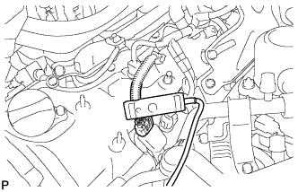
Connect the tester probe of a timing light to the wire of the ignition coil connector for the No. 1 cylinder.
Note
Use a timing light that detects primary signals.
-
Put the engine in inspection mode Click here.
-
Start the engine and idle it.
-
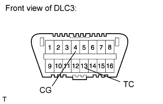
Using SST, connect terminals 13 (TC) and 4 (CG) of the DLC3.
- SST
- 09843-18040
Note
-
Confirm the terminal numbers before connecting the probes. Connecting the probe to the wrong terminal can damage the engine.
-
When checking the ignition timing, the transmission should be in neutral.
-
Using a timing light, check the ignition timing.
Standard ignition timing 8 to 12° BTDC @ idle (Transmission neutral position and A/C switch OFF) -
Remove SST from the DLC3.
-
Check the ignition timing.
Standard ignition timing 5 to 15° BTDC @ idle (Transmission neutral position and A/C switch OFF) -
Check that the ignition timing advances immediately when the engine speed is increased.
-
Disconnect the timing light from the engine.
-
Install the air cleaner case LH with the 2 nuts.
- Torque:
- 5.0 N*m { 51 kgf*cm, 44 in.*lbf }
-
Install the air cleaner filter element.
-
Connect the air cleaner cap sub-assembly LH.
-
Install the No. 1 air cleaner inlet with the 2 bolts.
- Torque:
- 5.0 N*m { 51 kgf*cm, 44 in.*lbf }
-
Install the engine room side cover LH Click here.
-
Install the air cleaner inlet cover with the 5 clips.
-
Install the V-bank cover.
-
-
-
INSPECT ENGINE IDLE SPEED
-
Put the engine in inspection mode Click here.
-
Warm up the engine.
Tech Tips
A warmed up engine should have an engine coolant temperature of over 80°C (176°F) and an engine oil temperature of 60°C (140°F), and the engine rpm should be stabilized.
-
When using the intelligent tester:
Note
Switch off all accessories and the A/C before connecting the intelligent tester.
-
Race the engine at 2500 rpm for approximately 90 seconds.
-
Enter the following menus: Powertrain / Engine and ECT / Data List / Primary / Engine Speed.
Tester Display Measurement Item/ Range Normal Condition Diagnostic Note Engine Speed Engine speed:
Min.: 0 rpm, Max.: 16383.75 rpm
800 to 900 rpm: Idling Shift lever on P 950 to 1050 rpm: Idling Shift lever on N Tech Tips
Refer to the intelligent tester operator's manual for further details.
If the idle speed is not as specified, check the air intake system.
-
Disconnect the intelligent tester from the DLC3.
-
-
When not using the intelligent tester:
Note
Switch off all accessories and the A/C before connecting the intelligent tester.
-
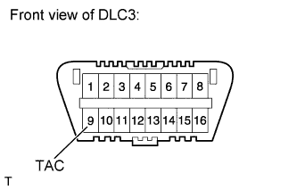
Using SST, connect a tachometer probe to terminal 9 (TAC) of the DLC3.
- SST
- 09843-18030
Note
Confirm the terminal number before connecting the probe. Connecting the probe to the wrong terminal can damage the engine.
-
Race the engine at 2500 rpm for approximately 90 seconds.
-
Check the idle speed.
Standard Idle Speed Condition Specified Condition Shift lever on P 800 to 900 rpm Shift lever on N 950 to 1050 rpm If the speed is not as specified, check the air intake system.
-
Disconnect the tachometer from the DLC3.
-
-
-
INSPECT COMPRESSION
-
Warm up and stop the engine.
Tech Tips
A warmed up engine should have an engine coolant temperature of over 80°C (176°F) and an engine oil temperature of 60°C (140°F), and the engine rpm should be stabilized.
-
Remove the luggage compartment mat and battery service hole cover LH.
-
Disconnect the cable from the auxiliary negative (-) battery terminal.
Note
When disconnecting the cable, some systems need to be initialized after the cable is reconnected Click here.
-
Remove the service plug grip Click here.
-
Remove the 8 spark plugs Click here.
Note
If an ignition coil assembly connector is disconnected, a DTC will be stored during inspection. Therefore, leave the ignition coil assembly connectors connected.
-
Connect the frame wire Click here.
-
Connect the generator cable Click here.
-
Connect the motor cable Click here.
-
Install the skid control ECU bracket with the 2 nuts and bolt.
- Torque:
- 8.5 N*m { 87 kgf*cm, 75 in.*lbf }
-
Connect the 3 skid control ECU connectors.
Tech Tips
If a DTC for the hybrid control system is output, the Active Test cannot be performed. Therefore, it is necessary to install the skid control ECU.
-
Install the skid control ECU with the 2 bolts and nut.
- Torque:
- 8.5 N*m { 87 kgf*cm, 75 in.*lbf }
-
Install the service plug grip Click here.
-
Connect the cable to the auxiliary negative (-) battery terminal.
-
Temporarily install the engine oil level dipstick guide with the bolt and insert the dipstick.
Note
Engine oil will overflow if the compression test is performed with the engine oil level dipstick guide uninstalled.
-
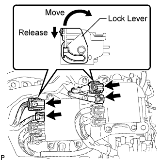
Disconnect the 4 injector driver connectors as shown in the illustration.
Tech Tips
To release each connector lock, push the claw downward ("Release" in the illustration) and move the lock lever ("Move" in the illustration).
-
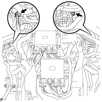
Disconnect the 2 injector connectors shown in the illustration.
-
Insert a compression gauge into the spark plug hole.
-
Connect the intelligent tester to the DLC3.
Note
Check the HV battery voltage in the data list to ensure that the battery is fully charged.
-
Turn the power switch on (IG).
-
Push the intelligent tester main switch on.
-
Enter the following menus: Powertrain / Hybrid Control / Active Test / Compress Test / On.
-
Fully depress the acceleration pedal.
-
Depress and hold the brake pedal, and turn the power switch on (READY). Then check the compression pressure.
Tech Tips
-
Noise may emit from the transmission. However, this is not a malfunction.
-
Always use a fully charged battery to obtain an engine speed of 200 rpm or more.
Note
The measurement must be done as quickly as possible.
Standard compression pressure 1000 kPa (10.2 kgf/cm2, 145 psi) or more Minimum pressure 700 kPa (7.1 kgf/cm2, 102 psi) -
-
Remove the compression gauge.
-
Perform the inspection above for each cylinder.
-
Check the pressure difference between each compression pressure.
Pressure difference 100 kPa (1.0 kgf/cm2, 15 psi) or less -
If the cylinder compression is low in one or more cylinders, pour a small amount of engine oil into the cylinder with low compression through its spark plug hole. Then inspect the cylinder compression pressure again.
Tech Tips
If adding oil helps boost the compression, it is likely that the piston rings and/or cylinder bore are worn or damaged.
If pressure stays low, a valve may be stuck or seated improperly, or there may be leakage in the gasket.
-
Disconnect the cable from the auxiliary negative (-) battery terminal.
-
Remove the service plug grip.
-
Remove the 2 bolts, nut and skid control ECU.
-
Disconnect the 3 skid control ECU connectors.
-
Remove the 2 nuts, bolt and skid control ECU bracket.
-
Disconnect the motor cable.
-
Disconnect the generator cable.
-
Disconnect the frame wire.
-
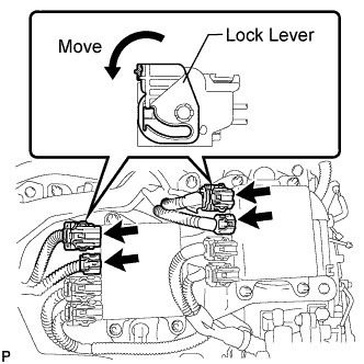
Connect the 4 injector driver connectors as shown in the illustration.
Note
Connect the connector securely.
Tech Tips
Move the lock lever in the direction indicated by the arrow to lock the connector.
-
Connect the 2 injector connectors.
-
Remove the dipstick, engine oil level dipstick guide and bolt.
-
Install the 8 spark plugs Click here.
-
Install the service plug grip.
-
Connect the cable to the auxiliary negative (-) battery terminal.
Note
When disconnecting the cable, some systems need to be initialized after the cable is reconnected Click here.
-
Install the luggage compartment mat and battery service hole cover LH.
-
Clear the DTCs Click here.
-
-
INSPECT CO/HC
Tech Tips
This check determines whether or not the idle CO/HC complies with regulations.
-
Put the engine in inspection mode Click here.
-
Warm up the engine.
Tech Tips
A warmed up engine should have an engine coolant temperature of over 80°C (176°F) and an engine oil temperature of 60°C (140°F), and the engine rpm should be stabilized.
-
Keep the engine speed at 2500 rpm for approximately 180 seconds.
-
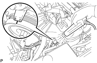
Insert the CO/HC meter testing probe at least 40 cm (1.31 ft.) into the tailpipe during idling.
-
Immediately check CO/HC concentration at idle and 2500 rpm.
Tech Tips
-
When performing the 2 mode (2500 rpm and idle) test, follow the measurement order prescribed by the applicable local regulations.
-
If the CO/HC concentration does not comply with regulations, troubleshoot in the order given below.
-
Check the air fuel ratio sensor Click here and heated oxygen sensor Click here operation.
-
See the table below for possible causes, then inspect and correct the applicable causes if necessary.
CO HC Symptom Causes Normal High Rough idle
-
1. Faulty ignitions
-
Incorrect timing
-
Plugs (contaminated, shorted, or gaps are defective)
-
2. Leaky intake and exhaust valves
-
3. Leaky cylinder
Low High Rough idle
(Fluctuating HC reading)
-
1. Vacuum leaks
-
PCV hose
-
Intake manifold
-
Throttle body
-
2. Lean mixture causing misfire
High High Rough idle
(Black smoke from exhaust)
-
1. Restricted air filter
-
2. Faulty SFI system
-
Faulty pressure
-
Defective engine coolant temperature sensor
-
Faulty ECM
-
Faulty injector
-
Faulty throttle position sensor
-
Faulty mass air flow meter
-
-
-