WIPER AND WASHER SYSTEM Rear Wiper does not Operate
DESCRIPTION
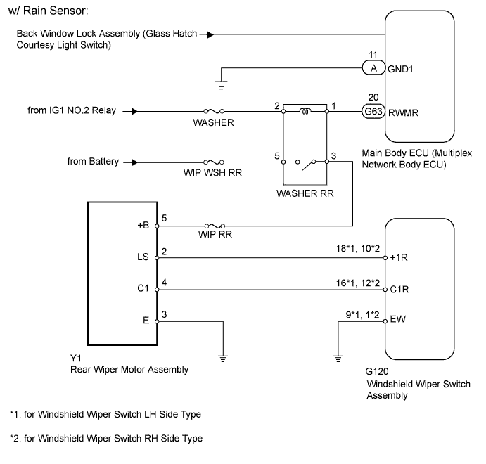
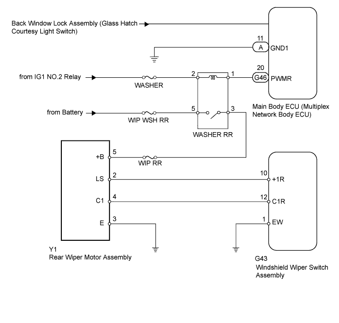
When the glass hatch is open, the rear wiper system cuts off the power supply to prevent the rear wiper and rear washer from operating.
WIRING DIAGRAM
INSPECTION PROCEDURE
Note
Inspect the fuses for circuits related to this system before performing the following inspection procedure.
PROCEDURE
-
READ VALUE USING INTELLIGENT TESTER (GLASS HATCH COURTESY SWITCH)
-
Use the Data List to check if the glass hatch opener is functioning properly Click here.
Main Body Tester Display Measurement Item/Range Normal Condition Diagnostic Note Glass Hatch Courtesy Switch Glass hatch courtesy switch signal / ON or OFF ON: Glass hatch open
OFF: Glass hatch closed
- OK On tester screen, each item changes between ON and OFF according to above chart.
NG 
GO TO LIGHTING SYSTEM Click here
OK 
-
-
PERFORM ACTIVE TEST USING INTELLIGENT TESTER (REAR WIPER MOTOR)
-
Using the intelligent tester, perform the Active Test Click here.
Main Body Tester Display Test Part Control Range Diagnostic Note Rear Wiper Power Supply WASHER RR relay operation ON/OFF - OK Rear wiper motor operates.
NG 
INSPECT WASHER RR RELAY Click here
OK 
REPLACE MAIN BODY ECU (MULTIPLEX NETWORK BODY ECU) Click here
-
-
INSPECT WASHER RR RELAY
-
Remove the WASHER RR relay from the engine room relay block, junction block.
-
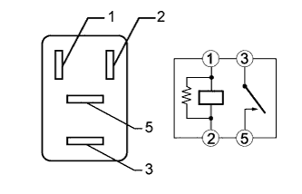
Measure the resistance according to the value(s) in the table below.
Standard Resistance Tester Connection Condition Specified Condition 3 - 5 Battery voltage is not applied to terminals 1 and 2 10 kΩ or higher Battery voltage is applied to terminals 1 and 2 Below 1 Ω
NG
REPLACE WASHER RR RELAY
OK
-
-
CHECK HARNESS AND CONNECTOR (WASHER RR RELAY - BATTERY)
-
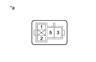
Text in Illustration *a Front view of wire harness connector
(to WASHER RR Relay)
Remove the WASHER RR relay from the engine room relay block, junction block.
-
Measure the voltage according to the value(s) in the table below.
Standard Voltage Tester Connection Switch Condition Specified Condition WASHER RR relay terminal 2 - Body ground Ignition switch ON 11 to 14 V WASHER RR relay terminal 2 - Body ground Ignition switch off Below 1 V WASHER RR relay terminal 5 - Body ground Always 11 to 14 V WASHER RR relay terminal 5 - Body ground Always Below 1 V
NG
REPAIR OR REPLACE HARNESS OR CONNECTOR
OK
-
-
CHECK HARNESS AND CONNECTOR (MAIN BODY ECU - RR WASHER RELAY AND BODY GROUND)
-
Remove the WASHER RR relay from the engine room relay block, junction block.
-
Remove the main body ECU Click here.
-
Measure the resistance according to the value(s) in the table below.
Standard Resistance Tester Connection Condition Specified Condition G63-20 (RWMR) - WASHER RR relay terminal 1 Always Below 1 Ω A-11 (GND1) - Body ground Always Below 1 Ω G63-20 (RWMR) - Body ground Always 10 kΩ or higher
NG
REPAIR OR REPLACE HARNESS OR CONNECTOR
OK
-
-
CHECK HARNESS AND CONNECTOR (WASHER RR RELAY - REAR WIPER MOTOR ASSEMBLY)
-
Disconnect the Y1 rear wiper motor connector.
-
Remove the WASHER RR relay from the engine room relay block, junction block.
-
Measure the resistance according to the value(s) in the table below.
Standard Resistance Tester Connection Condition Specified Condition Y1-5 (+B) - WASHER RR relay terminal 3 Always Below 1 Ω Y1-5 (+B) - Body ground Always 10 kΩ or higher
NG
REPAIR OR REPLACE HARNESS OR CONNECTOR
OK
-
-
INSPECT REAR WIPER MOTOR ASSEMBLY
-
Remove the rear wiper motor Click here.
-
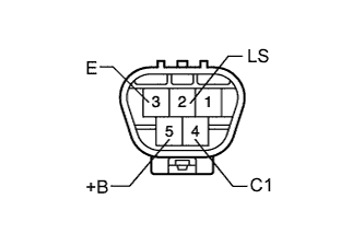
Check that the rear wiper motor assembly operates when the battery voltage is applied between the terminals.
OK Tester Connection Specified Condition Battery positive (+) → 5 (+B)
Battery negative (-) → 2 (LS)
Battery negative (-) → 3 (E)
Motor operates at low speed (LO) Battery positive (+) → 5 (+B)
Battery negative (-) → 4 (C1)
Battery negative (-) → 3 (E)
Rear wiper motor operates intermittently
NG
REPLACE REAR WIPER MOTOR ASSEMBLY Click here
OK
-
-
CHECK HARNESS AND CONNECTOR (REAR WIPER MOTOR ASSEMBLY - BODY GROUND)
-
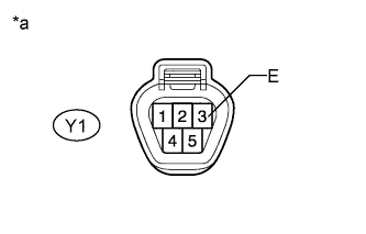
Text in Illustration *a Front view of wire harness connector
(to Rear Wiper Motor Assembly)
Disconnect the Y1 rear wiper motor connector.
-
Measure the resistance according to the value(s) in the table below.
Standard Resistance Tester Connection Condition Specified Condition Y1-3 (E) - Body ground Always Below 1 Ω
NG
REPAIR OR REPLACE HARNESS OR CONNECTOR
OK
-
-
INSPECT WINDSHIELD WIPER SWITCH ASSEMBLY
-
Remove the windshield wiper switch connector Click here.
-
Measure the resistance according to the value(s) in the table below.
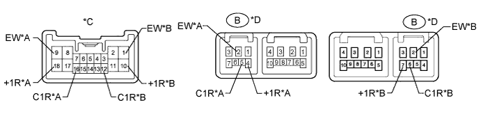
Standard Resistance for Windshield Wiper Switch LH Side Type w/ Rain Sensor Tester Connection Switch Condition Specified Condition 16 (C1R) - 9 (EW) OFF 10 kΩ or higher 18 (+1R) - 9 (EW) OFF 10 kΩ or higher 16 (C1R) - 9 (EW) LO Below 1 Ω 18 (+1R) - 9 (EW) HI Below 1 Ω w/o Rain Sensor Tester Connection Switch Condition Specified Condition B-5 (C1R) - B-2 (EW) OFF 10 kΩ or higher B-4 (+1R) - B-2 (EW) OFF 10 kΩ or higher B-5 (C1R) - B-2 (EW) LO Below 1 Ω B-4 (+1R) - B-2 (EW) HI Below 1 Ω for Windshield Wiper Switch RH Side Type w/ Rain Sensor Tester Connection Switch Condition Specified Condition 12 (C1R) - 1 (EW) OFF 10 kΩ or higher 10 (+1R) - 1 (EW) OFF 10 kΩ or higher 12 (C1R) - 1 (EW) LO Below 1 Ω 10 (+1R) - 1 (EW) HI Below 1 Ω w/o Rain Sensor Tester Connection Switch Condition Specified Condition B-6 (C1R) - B-2 (EW) OFF 10 kΩ or higher B-7 (+1R) - B-2 (EW) OFF 10 kΩ or higher B-6 (C1R) - B-2 (EW) LO Below 1 Ω B-7 (+1R) - B-2 (EW) HI Below 1 Ω Text in Illustration *A for Windshield Wiper Switch LH Side Type *B for Windshield Wiper Switch RH Side Type *C w/ Rain Sensor *D w/o Rain Sensor
NG
REPLACE WINDSHIELD WIPER SWITCH ASSEMBLY Click here
OK
-
-
CHECK HARNESS AND CONNECTOR (WINDSHIELD WIPER SWITCH ASSEMBLY - REAR WIPER MOTOR ASSEMBLY AND BODY GROUND)
-
for Windshield Wiper Switch LH Side Type:
-
Disconnect the Y1 rear wiper motor connector.
-
Disconnect the G120 or G43 windshield wiper switch connector.
-
Measure the resistance according to the value(s) in the table below.
Standard Resistance w/ Rain Sensor Tester Connection Condition Specified Condition Y1-2 (LS) - G120-18 (+1R) Always Below 1 Ω Y1-4 (C1) - G120-16 (C1R) Always Below 1 Ω G120-9 (EW) - Body ground Always Below 1 Ω Y1-2 (LS) - Body ground Always 10 kΩ or higher Y1-4 (C1) - Body ground Always 10 kΩ or higher w/o Rain Sensor Tester Connection Condition Specified Condition Y1-2 (LS) - G43-4 (+1R) Always Below 1 Ω Y1-4 (C1) - G43-5 (C1R) Always Below 1 Ω G43-2 (EW) - Body ground Always Below 1 Ω Y1-2 (LS) - Body ground Always 10 kΩ or higher Y1-4 (C1) - Body ground Always 10 kΩ or higher
-
-
for Windshield Wiper Switch RH Side Type:
-
Disconnect the Y1 rear wiper motor connector.
-
Disconnect the G120 or G43 windshield wiper switch connector.
-
Measure the resistance according to the value(s) in the table below.
Standard Resistance w/ Rain Sensor Tester Connection Condition Specified Condition Y1-2 (LS) - G120-10 (+1R) Always Below 1 Ω Y1-4 (C1) - G120-12 (C1R) Always Below 1 Ω G120-1 (EW) - Body ground Always Below 1 Ω Y1-2 (LS) - Body ground Always 10 kΩ or higher Y1-4 (C1) - Body ground Always 10 kΩ or higher w/o Rain Sensor Tester Connection Condition Specified Condition Y1-2 (LS) - G43-7 (+1R) Always Below 1 Ω Y1-4 (C1) - G43-6 (C1R) Always Below 1 Ω G43-2 (EW) - Body ground Always Below 1 Ω Y1-2 (LS) - Body ground Always 10 kΩ or higher Y1-4 (C1) - Body ground Always 10 kΩ or higher
-
NG
REPAIR OR REPLACE HARNESS OR CONNECTOR
OK
REPLACE MAIN BODY ECU (MULTIPLEX NETWORK BODY ECU) Click here
-