FRONT DOOR REASSEMBLY

Tech Tips
-
Use the same procedure for RHD and LHD vehicles.
-
The procedure listed below is for LHD vehicles.
-
Use the same procedure for the RH and LH sides.
-
The procedure listed below is for the LH side.
-
A bolt without a torque specification is shown in the standard bolt chart Click here.
-
INSTALL FRONT DOOR PANEL CUSHION
-
Attach the clip to install a new door panel cushion.
-
-
REPAIR INSTRUCTION
-
Clean the vehicle body surface.
-
Using a heat light, heat the vehicle body surface.
-
Wipe off any tape adhesive residue with cleaner.
-
-
Installation temperature.
-
When the ambient temperature is below 15°C (59°F), perform the installation procedure after warming the vehicle body surface (installation surface of the door frame) and tape to between 20 and 30°C (68 and 86°F) using a heat light. When the ambient temperature is higher than 35°C (95°F), cool the vehicle body surface (installation surface of the door frame) and tape to between 20 and 30°C (68 and 86°F) prior to installation.
Tech Tips
-
The most appropriate temperature for installing the tape is 25°C (77°F).
-
When the temperature is low, the tape turns stiff and falls off easily. When the temperature is high, the tape loses elasticity.
-
-
-
Before installation.
-
Make sure any dirt on and around the vehicle body surface where the tape will be installed (installation surface of the door frame) is removed, and that the surface is smooth. If the surface is rough or dirt remains when pressing the tape onto the surface, air will be trapped under the tape and result in a poor appearance.
Tech Tips
Spray water on the shop floor to settle any dust.
-
-
Key points for handling the tape.
-
The tape bends and rolls up easily. Store the tape between flat pieces of cardboard or other similar objects and keep it dry and level.
Note
Do not bend the tape or leave it in a place with a high temperature.
-
-
Key points for the installation of the tape (how to use a squeegee and the installation procedure for a flat surface).
Note
-
Position the tape with a high level of accuracy to achieve a neat finish and to avoid peeling.
-
The tape cannot be reused because it deforms and will not fit after removal.
-
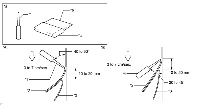
To avoid air bubbles, slightly raise the part of the tape that is going to be applied so that its adhesive surface does not touch the vehicle body while applying the tape. Tilt the squeegee 40 to 50° (for pressing forward) or 30 to 45° (for pulling) from the vehicle body surface and press with a force of 20 to 30 N (2 to 3 kgf) while moving the squeegee at a constant slow speed of 3 to 7 cm (1.2 to 2.8 in.) per second.
Note
Be sure to observe the specified pressing speed, force and angle of the squeegee to avoid wrinkles and air bubbles.
Tech Tips
-
Either angle of the squeegee (for pressing forward or for pulling) is acceptable.
-
Be sure to apply the tape while removing the release paper 10 to 20 mm (0.393 to 0.787 in.) from the edge of the squeegee.
Text in Illustration *A Pressing *B Pulling *1 Squeegee *2 Black Out Tape *3 Release Paper - - *a Sectional View *b Non-padded Side *c Padded Side - - -
-
-
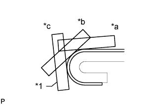
Text in Illustration *1 Squeegee *a First *b Second *c Third Key points for the installation of the tape (how to use a squeegee and the installation procedure for hemming surfaces).
-
If it is difficult to press the tape, press it in several steps as shown in the illustration. Use your fingers or the padded surface of a squeegee to slowly apply the tape to the hem of the vehicle, especially for a small hem.
Tech Tips
When applying tape to the backside of a hem, remove the release paper and use your fingers or the padded surface of a squeegee.
-
-
Key points for the installation of the tape (how to use a squeegee and the installation procedure for corners).
-
Remove the release paper and apply the tape carefully with your fingers.
-
Before applying the tape to each corner, heat the tape using a heat light and gradually apply it to avoid wrinkles in the tape and achieve a neat finish.
-
-
Check after installation.
-
After completing the application, check if the tape is applied neatly. If the tape is not applied neatly, apply new tape.
Note
Do not reuse the tape.
-
-
-
INSTALL LOWER FRONT DOOR OUTSIDE STRIPE LH
-
Refer to the illustration to position a new lower front door outside stripe.
Reference Value Area Specified Condition A +/-1.0 mm (0.039 in.) from End
-
-
INSTALL FRONT DOOR OUTSIDE STRIPE LH
-
Refer to the illustration to position a new front door outside stripe.
Reference Value Area Specified Condition A +/-1.0 mm (0.039 in.) from End
-
-
INSTALL NO. 1 BLACK OUT TAPE LH
-
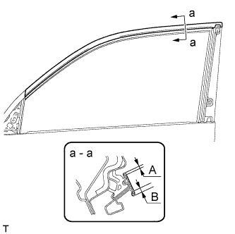
Refer to the illustration to position a new black out tape.
Reference Value Area Specified Condition A 2 to 4 mm (0.078 to 0.158 in.) B 4 to 6 mm (0.157 to 0.236 in.)
-
-
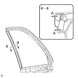
INSTALL FRONT DOOR REAR WINDOW FRAME MOULDING LH
-
Clean the vehicle body surface.
-
Using a heat light, heat the vehicle body surface.
-
Remove the double-sided tape from the vehicle body surface.
-
Wipe off any tape adhesive residue with cleaner.
-
-
Install a new front door rear window frame moulding.
-
Using a heat light, heat a new front door rear window frame moulding and the vehicle body surface.
-
Remove the peeling paper from the face of the front door rear window frame moulding.
Tech Tips
After removing the peeling paper, keep the exposed adhesive free from foreign matter.
-
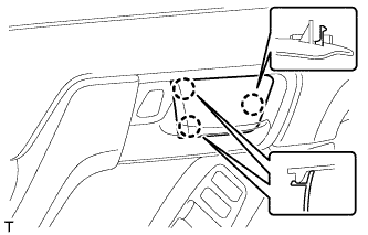
Attach the clip and double-sided tape to install the front door rear window frame moulding.
Tech Tips
Press the front door rear window frame moulding firmly to install it.
-
-
Install a new door window frame moulding clip.
-
-
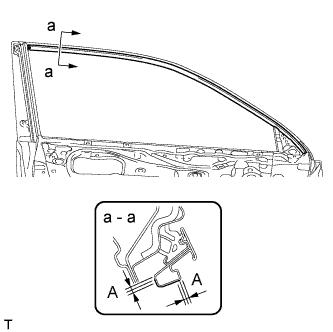
INSTALL FRONT DOOR BELT MOULDING LH
-
Attach the 6 claws to install the front door belt moulding.
-
-
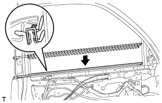
INSTALL FRONT DOOR WEATHERSTRIP LH
-
Attach the 21 clips to install a new front door weatherstrip.
-
-
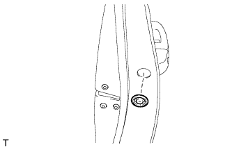
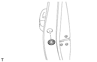
INSTALL FRONT DOOR CHECK ASSEMBLY LH
-
Apply MP grease to the sliding areas of the front door check assembly.
-
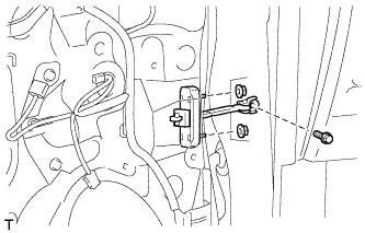
Install the door check to the door panel with the 2 nuts.
- Torque:
- 8.0 N*m { 82 kgf*cm, 71 in.*lbf }
-
Apply adhesive to the threads of the bolt.
Adhesive Toyota Genuine Adhesive 1324, Three Bond 1324 or equivalent -
Install the front door check assembly with the bolt.
- Torque:
- 27 N*m { 275 kgf*cm, 20 ft.*lbf }
-
-
INSTALL FRONT DOOR NO. 2 STIFFENER CUSHION
-
Clean the installation surface.
-
Using a heat light, heat the installation surface.
Standard Item Temperature Vehicle body 40 to 60°C (104 to 140°F) Note
Do not heat the vehicle body excessively.
-
Remove the double-sided tape from the installation surface.
-
Wipe off any tape adhesive residue with cleaner.
-
-
Install a new door stiffener cushion.
-
Using a heat light, heat a new front door No. 2 stiffener cushion and the installation surface.
Tech Tips
When installing the front door No. 2 stiffener cushion, heat the vehicle body and door stiffener cushion using a heat light.
Standard Item Temperature Door stiffener cushion 20 to 30°C (68 to 86°F) Vehicle body 40 to 60°C (104 to 140°F) Note
Do not heat the door stiffener cushion and vehicle body excessively.
-
Remove the peeling paper from the face of the door stiffener cushion.
Tech Tips
After removing the peeling paper, keep the exposed adhesive free from foreign matter.
-
Attach the 2 clamps and double-sided tape to install the front door No. 2 stiffener cushion.
Tech Tips
Press the front door No. 2 stiffener cushion firmly to install it.
-
Install the 2 bolts.
-
-
-
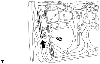
INSTALL FRONT DOOR LOCK OPEN ROD LH
-
Install the front door lock open rod as indicated by the arrows in the order shown in the illustration.
-
-
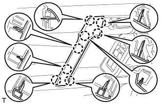
INSTALL FRONT DOOR NO. 2 WIRE LH (w/ Smart Entry and Start System)
-
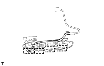
Attach the 4 clamps to install the front door No. 2 wire.
-
-
INSTALL FRONT DOOR OUTSIDE HANDLE FRAME SUB-ASSEMBLY LH
-
Apply MP grease to the sliding parts of the front door outside handle frame sub-assembly.
-
Attach the door handle nut and claw.
-
Using a T30 "TORX" socket wrench, install the front door outside handle frame sub-assembly with the screw.
- Torque:
- 4.0 N*m { 41 kgf*cm, 35 in.*lbf }
-
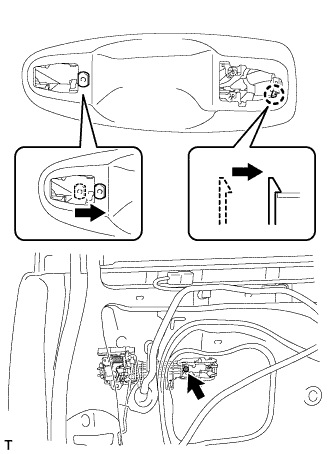
w/ Entry and Start System:
-
Attach the clamp.
-
Connect the front door No. 2 wire connector to the front door wire.
-
-
-
INSTALL FRONT DOOR REAR OUTSIDE HANDLE PAD LH
-
Attach the 2 claws to install the front door rear outside handle pad.
-
-
INSTALL FRONT DOOR FRONT OUTSIDE HANDLE PAD LH
-
Attach the 3 claws to install the front door front outside handle pad.
-
-
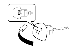
INSTALL FRONT DOOR OUTSIDE HANDLE ASSEMBLY LH
-
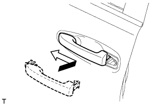
Insert the front end of the front door outside handle assembly into the front door outside handle frame.
-
Insert the rear end of the front door outside handle assembly into the front door outside handle frame, and then slide the front door outside handle assembly toward the front of the vehicle to install it.
-
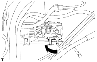
Move the lever in the direction indicated by the arrow in the illustration to lock the door outside handle assembly.
-
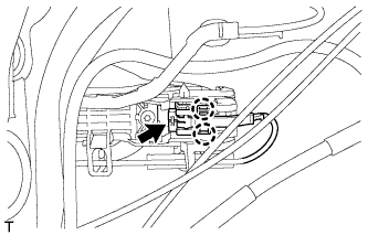
Connect the connector.
-
Attach the 2 claws.
-
-
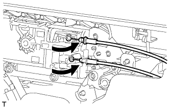
INSTALL FRONT DOOR INSIDE LOCKING CABLE ASSEMBLY LH
-
Install the front door inside locking cable assembly.
-
Attach the 3 claws.
-
-
INSTALL FRONT DOOR LOCK REMOTE CONTROL CABLE ASSEMBLY LH
-
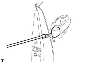
Install the front door lock remote control cable assembly.
-
-
INSTALL FRONT DOOR LOCK ASSEMBLY LH
Note
-
When reusing the removed front door lock assembly, replace the door lock wiring harness seal on the connector with a new one.
-
Do not allow grease or dust to adhere to the surface of the connector which contacts the door lock wiring harness seal.
-
Reusing the door lock wiring harness seal or using a damaged door lock wiring harness seal may allow water into the connection. This may result in a malfunction of the front door lock assembly.
-
Apply MP grease to the sliding parts of the front door lock assembly.
-
Install a new door lock wiring harness seal to the front door lock assembly.
-
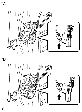
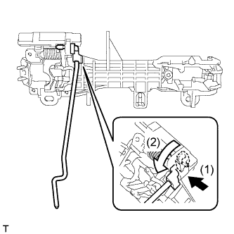
Text in Illustration *A w/o Double Locking System *B w/ Double Locking System 
Slide Insert the front door lock open rod to the front door lock assembly.
-
Check that the front door lock open rod is securely connected to the front door lock assembly.
-
Using a T30 "TORX" wrench, install the front door lock assembly with the 3 screws.
- Torque:
- 5.0 N*m { 51 kgf*cm, 44 in.*lbf }
-
Connect the connector.
-
-
INSTALL FRONT DOOR OUTSIDE HANDLE COVER RH (for Front Passenger Side)
-
Using a T30 "TORX" socket wrench, install the front door outside handle cover with the screw.
- Torque:
- 4.0 N*m { 41 kgf*cm, 35 in.*lbf }
-
Install the hole plug.
-
-
INSTALL FRONT DOOR OUTSIDE HANDLE COVER LH (for Driver Side)
-
Attach the claw to install the front door outside handle cover to the front door lock cylinder.
-
-
INSTALL FRONT DOOR OUTSIDE HANDLE COVER WITH LOCK CYLINDER ASSEMBLY (for Driver Side)
-
Install the front door outside handle cover with lock cylinder assembly.
Tech Tips
Make sure that the front door lock cylinder rod is inserted into the front door lock assembly.
-
Using a T30 "TORX" socket wrench, install the front door lock cylinder with the screw.
- Torque:
- 4.0 N*m { 41 kgf*cm, 35 in.*lbf }
-
Install the hole plug.
-
-
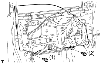
INSTALL FRONT DOOR REAR LOWER FRAME SUB-ASSEMBLY LH
-
Install the front door rear lower frame sub-assembly with the bolt as shown in the illustration.
-
-
INSTALL FRONT DOOR GLASS RUN LH
-
Install the front door glass run.
-
-
INSTALL DOOR FRAME GARNISH LH
-
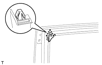
Attach the clip to install a new door frame garnish.
-
-
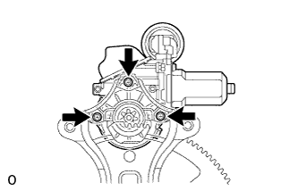
INSTALL FRONT POWER WINDOW REGULATOR MOTOR ASSEMBLY LH
-
Apply MP grease to the sliding and rotating areas of the regulator motor.
-
Using a T25 "TORX" socket wrench, install the power window regulator motor with the 3 screws.
- Torque:
- 5.4 N*m { 55 kgf*cm, 48 in.*lbf }
Tech Tips
A new front window regulator uses self-tapping screws to thread new installation holes when the self-tapping screws are inserted.
-
-
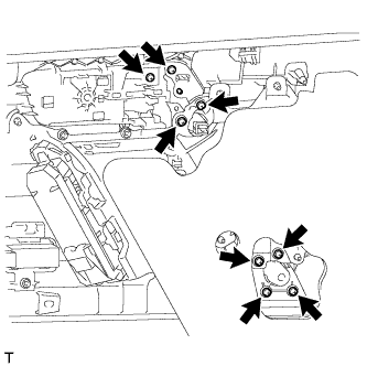
INSTALL FRONT DOOR WINDOW REGULATOR SUB-ASSEMBLY LH
-
Apply MP grease to the sliding parts of the front door window regulator assembly.
-
Install the temporary bolt to the front door window regulator assembly.
-
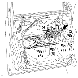
Text in Illustration *1 Temporary Bolt Temporarily install the front door window regulator assembly with the temporary bolt.
-
Temporarily install the 5 bolts, and then tighten the temporary bolt and 5 bolts.
- Torque:
- 8.0 N*m { 82 kgf*cm, 71 in.*lbf }
Tech Tips
Tighten the bolts in the order shown in the illustration.
-
Connect the connector.
-
-
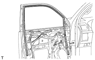
INSTALL FRONT DOOR GLASS SUB-ASSEMBLY LH
-
Connect the cable to the negative (-) battery terminal.
-
Connect the power window regulator master switch assembly and move the front door glass sub-assembly so that the door glass bolt installation locations can be seen.
-
Disconnect the cable from the negative (-) battery terminal and power window regulator master switch assembly.
CAUTION:
Wait at least 90 seconds after disconnecting the cable from the negative (-) battery terminal to disable the SRS system Click here.
-
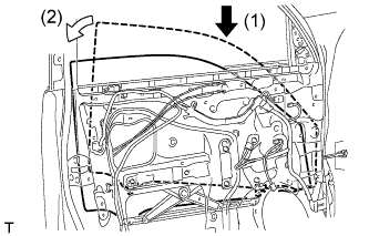
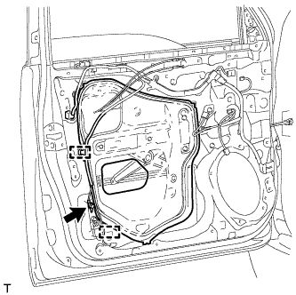
Insert the front door glass sub-assembly into the front door panel along the front door glass run as indicated by the arrows in the order shown in the illustration.
-
Install the front door glass sub-assembly with the 2 bolts.
- Torque:
- 5.5 N*m { 56 kgf*cm, 49 in.*lbf }
Tech Tips
Tighten the bolts in the order shown in the illustration.
-
-
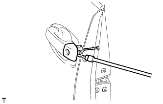
INSTALL OUTER REAR VIEW MIRROR ASSEMBLY LH
-
Attach the claw to install the outer rear view mirror, and then install the 3 nuts.
- Torque:
- 8.0 N*m { 82 kgf*cm, 71 in.*lbf }
-
Connect the connector.
-
-
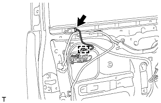
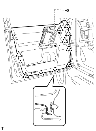
INSTALL FRONT DOOR SERVICE HOLE COVER LH
-
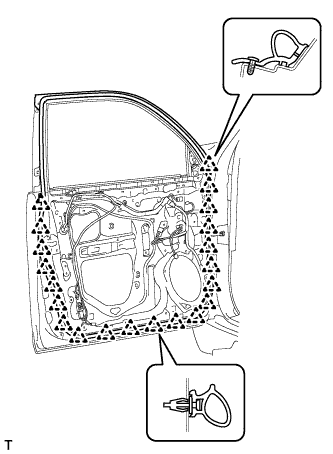
Apply new butyl tape to the front door panel.
-
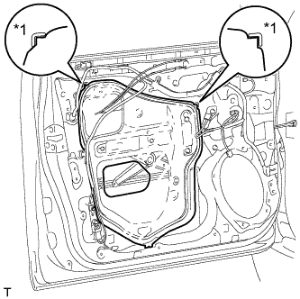
Text in Illustration *1 Reference Point Pass the front door lock remote control cable assembly and front door inside locking cable assembly through a new front door service hole cover.
-
Attach the front door service hole cover using the reference points on the front door panel.
Note
-
There should be no wrinkles or folds after attaching the service hole cover.
-
After attaching the service hole cover, check the seal quality.
Note
Securely install the front door service hole cover preventing wrinkles and air bubbles.
-
-
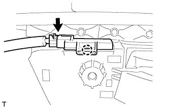
Attach the 2 clamps.
-
Install the bolt to the front door wire.
-
-
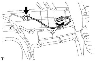
INSTALL SIDE AIRBAG SENSOR ASSEMBLY LH
-
Check that the ignition switch is off.
-
Check that the cable is disconnected from the negative (-) battery terminal.
CAUTION:
Wait at least 90 seconds after disconnecting the cable from the negative (-) battery terminal to disable the SRS system.
-
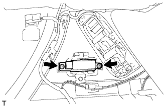
Install the side airbag sensor with the bolt.
- Torque:
- 9.0 N*m { 92 kgf*cm, 80 in.*lbf }
Note
-
If the side airbag sensor has been dropped, or there are any cracks, dents or other defects in the case, bracket or connector, replace it with a new one.
-
When installing the side airbag sensor, be careful that the SRS wiring does not interfere with other parts and that it is not pinched between other parts.
-
Check that the side airbag sensor is not loose.
-
Connect the connector.
-
-
INSTALL FRONT NO. 1 SPEAKER ASSEMBLY
-
Temporarily install the speaker by attaching the 2 claws of the speaker to the door panel.
-
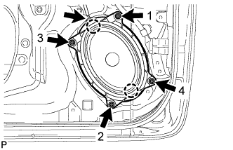
Install the speaker with the 4 screws in the order shown in the illustration.
-
Connect the speaker connector.
Note
Do not touch the cone of the speaker.
-
-
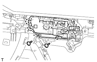
INSTALL SEAT MEMORY SWITCH (w/ Seat Position Memory System)
-
Install the switch with the 2 screws.
-
-
INSTALL FRONT DOOR INSIDE HANDLE SUB-ASSEMBLY LH
-
Attach the guide and 2 claws to install the front door inside handle sub-assembly to the front door trim board sub-assembly.
-
Install the 2 screws.
-
Install the 8 screws to the door assist grip assembly LH.
-
-
INSTALL POWER WINDOW REGULATOR SWITCH ASSEMBLY (for Front Passenger Side)
-
Attach the 2 claws to install the power window regulator switch assembly.
-
-
INSTALL MULTIPLEX NETWORK MASTER SWITCH ASSEMBLY (for Driver Side)
-
Install the multiplex network master switch assembly with the 3 screws.
-
-
INSTALL FRONT DOOR INSIDE HANDLE ILLUMINATION LIGHT ASSEMBLY LH
-
Attach the claw to install the light.
-
Connect the connector.
-
-
INSTALL NO. 2 INTERIOR ILLUMINATION LIGHT SUB-ASSEMBLY
-
Turn the light in the direction indicated by the arrow to install it.
-
Attach the clamp.
-
Connect the connector.
-
-
INSTALL FRONT REFLEX REFLECTOR ASSEMBLY
-
Attach the 2 claws to install the front reflex reflector assembly.
-
-
INSTALL FRONT DOOR INNER GLASS WEATHERSTRIP LH
-
Install the front door inner glass weatherstrip.
-
-
INSTALL FRONT DOOR TRIM BOARD SUB-ASSEMBLY LH
-
Connect the front door lock remote control cable assembly and front door inside locking cable assembly.
-
Connect 2 connectors.
-
w/ Seat Position Memory System:
-
Connect the connectors.
-
-
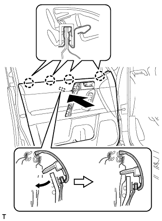
Attach the front door trim board sub-assembly by attaching the 4 claws of the front door inner glass weatherstrip as shown in the illustration.
-
Attach the 12 clips and front door trim board retainer to install the front door trim board sub-assembly.
-
Install the 3 screws.
-
-
INSTALL ASSIST GRIP COVER LH
-
Attach the 8 claws to install the assist grip cover.
-
-
INSTALL NO. 2 DOOR INSIDE HANDLE BEZEL LH
-
Attach the 3 claws to install the inside handle bezel.
-
-
INSTALL FRONT DOOR LOWER FRAME BRACKET GARNISH LH
-
Attach the 2 claws to install the front door lower frame bracket garnish.
-
-
CONNECT CABLE TO NEGATIVE BATTERY TERMINAL
Note
When disconnecting the cable, some systems need to be initialized after the cable is reconnected Click here.
-
INITIALIZE POWER WINDOW CONTROL SYSTEM
-
Initialize the power window Click here.
-
-
CHECK SRS WARNING LIGHT
-
Check the SRS warning light Click here.
-
-
ADJUST SIDE TELEVISION CAMERA ASSEMBLY (w/ Side Monitor System)
Tech Tips
Adjust the side television camera for the passenger side only.
-
Adjust the side television camera Click here.
-