HOOD LOCK CONTROL CABLE ASSEMBLY INSTALLATION

Tech Tips
A bolt without a torque specification is shown in the standard bolt chart Click here.
-
INSTALL HOOD LOCK CONTROL CABLE ASSEMBLY (for LHD)
-
Pass the hood lock control cable assembly into the engine compartment.
-
Pass the cable through the upper radiator support.
-
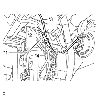
Attach the clamps as shown in the illustration.
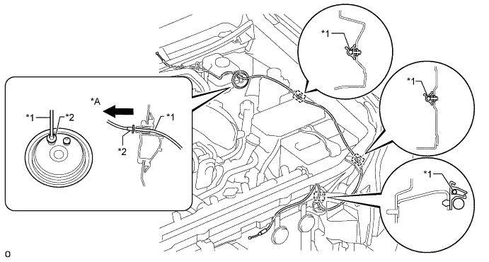
Text in Illustration *A for Engine Room Side - - *1 Hood Lock Control Cable *2 Stopper
-
-
INSTALL HOOD LOCK CONTROL CABLE ASSEMBLY (for RHD)
-
Pass the hood lock control cable assembly into the engine compartment.
-
Pass the cable through the upper radiator support.
-
Attach the clamps as shown in the illustration.
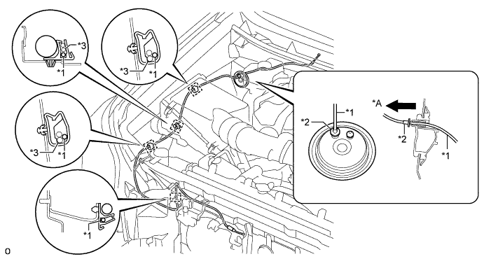
Text in Illustration *A for Engine Room Side - - *1 Hood Lock Control Cable *2 Stopper
-
-
INSTALL HOOD LOCK CONTROL LEVER SUB-ASSEMBLY
-
for LHD:
-
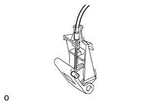
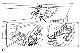
Connect the hood lock control cable assembly to the hood lock control lever sub-assembly.
-
Attach the 3 claws to install the hood lock control lever sub-assembly.
-
Text in Illustration *1 Protector *2 Fuel Lid Lock Control Cable *3 Hood Lock Control Cable *4 Clamp Attach the clamps as shown in the illustration.
-
-
for RHD:
-
Connect the hood lock control cable assembly to install the hood lock control lever sub-assembly.
-
Attach the 3 claws and install the hood lock control lever sub-assembly.
-
-
-
INSTALL HOOD LOCK ASSEMBLY (for LHD)
-
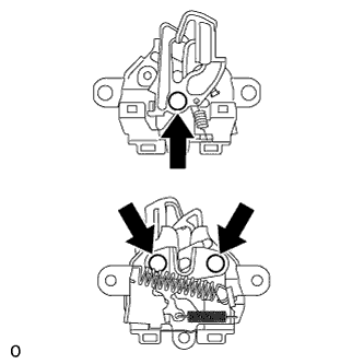
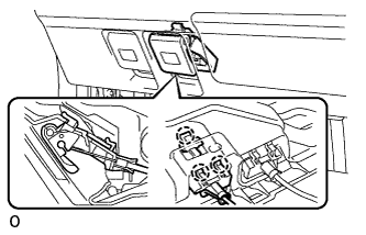
Apply MP grease to the sliding areas of the lock.
-
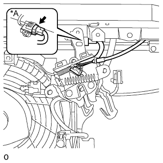
Text in Illustration *A w/ Engine Hood Courtesy Switch Connect the hood lock control cable assembly.
-
w/ Engine Hood Courtesy Switch:
Connect the connector.
-
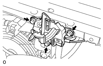
Install the hood lock assembly with the 3 bolts.
- Torque:
- 7.5 N*m { 76 kgf*cm, 66 in.*lbf }
-
-
INSTALL HOOD LOCK ASSEMBLY (for RHD)
-
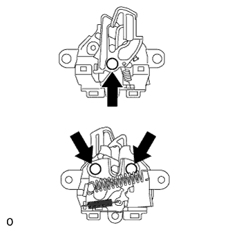
Apply MP grease to the sliding areas of the lock.
-
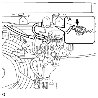
Text in Illustration *A w/ Engine Hood Courtesy Switch Connect the hood lock control cable assembly.
-
w/ Engine Hood Courtesy Switch:
Connect the connector.
-

Install the hood lock assembly with the 3 bolts.
- Torque:
- 7.5 N*m { 76 kgf*cm, 66 in.*lbf }
-
-
INSTALL HOOD LOCK CONTROL CABLE COVER
-
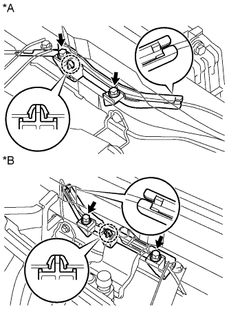
Text in Illustration *A for LHD *B for RHD Pass the hood lock control cable assembly through the hood lock control cable cover.
-
Attach the claw to install the hood lock control cable cover.
-
Install the 2 bolts.
- Torque:
- 7.5 N*m { 76 kgf*cm, 66 in.*lbf }
-
-
INSTALL LOW PITCHED HORN ASSEMBLY (for LHD)
-
Install the low pitched horn assembly with the bolt.
- Torque:
- 19 N*m { 194 kgf*cm, 14 ft.*lbf }
-
Connect the connector.
-
-
INSTALL HIGH PITCHED HORN ASSEMBLY (for LHD)
-
Install the high pitched horn assembly with the bolt.
- Torque:
- 19 N*m { 194 kgf*cm, 14 ft.*lbf }
-
Connect the connector.
-
-
INSTALL HOOD LOCK RELEASE LEVER PROTECTOR
-
Attach the 2 claws and 2 guides to install the hood lock release lever protector.
-
-
INSTALL MILLIMETER WAVE RADAR SENSOR ASSEMBLY (w/ Dynamic Radar Cruise Control System)
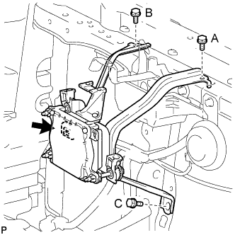
-
Connect the connector.
-
Attach the 2 guides.
-
Install the millimeter wave radar sensor assembly with the 3 bolts in alphabetical order.
- Torque:
- 5.5 N*m { 56 kgf*cm, 49 in.*lbf }
-
-
INSTALL RADIATOR GRILLE
-
Attach the 8 claws to install the radiator grille.
-
Install the 4 screws.
-
-
ADJUST MILLIMETER WAVE RADAR SENSOR ASSEMBLY (w/ Dynamic Radar Cruise Control System)

Text in Illustration *a Approximately. 10 m (32.8 ft.) *b Approximately. 14 m (45.9 ft.) CAUTION:
Exposure to radio frequency emissions is hazardous to your health. It is hazardous to be within 20 cm (7.87 in.) of the radio frequency aperture of the device.
Note
-
This device complies with FCC radio frequency emission regulations.
-
Perform adjustment on a level surface.
-
Make sure that no large pieces of metal are within a 10 m (32.8 ft.) x 14 m (45.9 ft.) area in front of the vehicle. If possible, the surrounding area should also be free of large metal objects.
-
Before adjusting the radar beam axis, prepare the vehicle as follows.
-
Check the tire pressure and adjust it if necessary.
-
Remove all excess weight from the vehicle (luggage, heavy objects, etc.).
-
-
Check and adjust the vertical direction of the radar sensor.
-
Text in Illustration *1 Level Remove dust, oil and foreign matter from the level rack of the radar sensor.
-
Set a level on the level rack of the radar sensor.
-
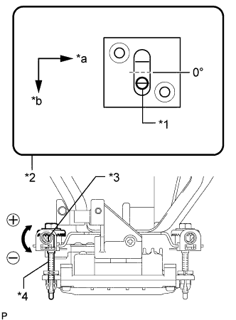
Text in Illustration *1 Air Bubble *2 Level *3 Screwdriver Insertion Hole *4 Bolt A *a LH *b FR Check that the level's air bubble is within the red frame.
OK Level's air bubble is within red frame. If the bubble is not within the red frame, use a screwdriver to adjust bolt A until the level's air bubble is within the red frame.
Tech Tips
-
The adjustable range within the red frame of the level is +/-0.2°.
-
The target angle is +0.2° (upward angle of 0.2°).
Result Adjustment Direction Adjustment Procedure Adjustment Angle (Reference) Vertical adjustment Upward direction: Turn bolt A to negative (-) side For every rotation of screwdriver, sensor moves approximately 0.12 ° Downward direction: Turn bolt A to positive (+) side -
-
-
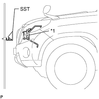
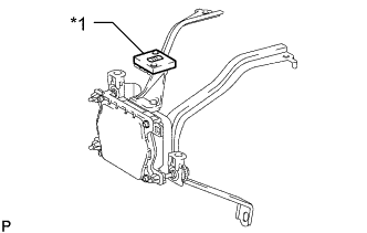
Text in Illustration *1 Millimeter Wave Radar Sensor Assembly Adjust the reflector height.
-
Adjust the reflector so that the center of SST reflector is the same height as the millimeter wave radar sensor.
- SST
- 09870-60000 ( 09870-60010 )
- 09870-60040
Tech Tips
Prepare a string that is more than 10 m (32.8 ft.) long with a sharp-pointed weight (plumb bob), and a 5 m (16.4 ft.) tape measure.
-
-
Place the reflector.
-
From the center of the front bumper (center of the emblem), hang a weight with a pointed tip, and mark point B on the ground.
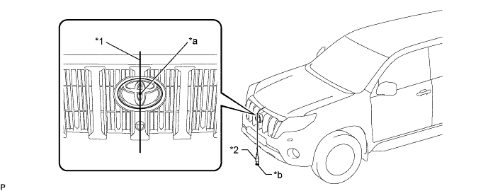
Text in Illustration *1 String *2 Weight *a Center *b Point B -
From the center of the rear bumper (center of the emblem), hang a weight with a pointed tip, and mark point A on the ground.
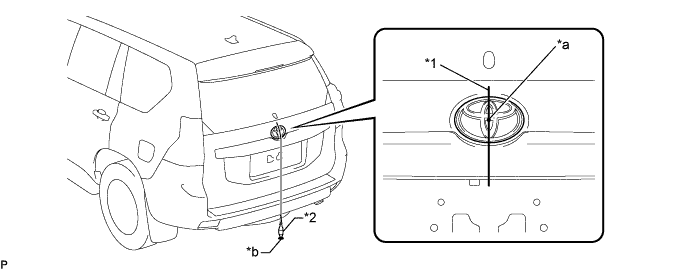
Text in Illustration *1 String *2 Weight *a Center *b Point A -
Using a piece of string that uses point A as a starting point and that passes through point B, make a straight line on the ground ahead of the vehicle 5 m (16.4 ft.) or more from point B.
Tech Tips
-
Make sure to secure the string (using tape, etc.) when it is taut.
-
Lightly flick the string with your fingers several times to confirm that the string is aligned above point B.
-
-
Mark point C at a location 5000 mm (16.4 ft.) from point B.
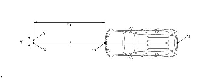
Text in Illustration *a Point A *b Point B *c Point C *d Point D (SST (Reflector) Placement Position) *e 5000 mm (16.4 ft.) *f 19.2 mm (0.756 in.) -
Mark point D at a location 19.2 mm (0.756 in.) from point C.
-
Place SST (reflector) at point D.
Note
Perform the operation as precisely as possible.
-
-
Check the radar beam axis.
Tech Tips
If a screen indicating an error is displayed while performing this procedure, perform the procedure again from *1.
-
Connect the intelligent tester to the DLC3.
-
Turn the ignition switch to ON.
-
Turn the intelligent tester main switch on, and turn the cruise control main switch on.
-
Select "Auto" from the intelligent tester display screen.*1
-
Select "Radar Cruise" from the display screen.
-
Select "Utility" from the display screen.
-
Select "Beam Axis Adjustment" from the display screen.
-
Follow the tester display and select "Next".
Note
-
Turn the cruise control main switch on before pressing Next.
-
Make sure there is at least 20 cm (7.87 in.) between the radar sensor and any nearby individuals.
CAUTION:
Do not come within 20 cm (7.87 in.) of the radar sensor.
-
-
Check the following items on the radar cruise divergence data screen.
CAUTION:
While using the beam axis adjustment mode of the intelligent tester, the actual direction and angle of the radar sensor may be different from the data on the intelligent tester. In such a case, the deviation is displayed on the multi-information display of the combination meter.
-
Confirm that the distance is approximately 5 m (16.4 ft.).
Tech Tips
-
A value between 0.0 and 6.3 m (20.7 ft.) is indicated.
-
If the distance is 0 m (0 ft.), the sensor cannot detect the target. Reconfirm that there is no metal in the specified area in front of the vehicle (refer to the NOTICE at the beginning of this adjustment procedure).
-
-
Confirm that the left/right side value is between 0.0 and 6.3 m (20.7 ft.).
Tech Tips
If the distance is 0 m (0 ft.), the sensor cannot detect the target. Reconfirm that there is no metal in the specified area in front of the vehicle (refer to the NOTICE at the beginning of this adjustment procedure).
-
-
-
Check and adjust the horizontal direction of the radar sensor.
-
Check that the divergence of the radar beam axis is 0°.
Standard 0° (Both right and left) If the axis is not as specified, use a screwdriver to adjust bolt B until the divergence of the radar beam axis is 0°.
-
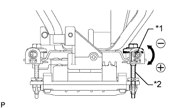
Text in Illustration *1 Screwdriver Insertion Hole *2 Bolt B Using a screwdriver, turn and adjust bolt B for horizontal adjustment of the millimeter wave radar sensor based on the measured divergence of the beam axis.
Result Adjustment Direction Adjustment Procedure Adjustment Angle (Reference) Horizontal adjustment Right direction: Turn bolt B to positive (+) side For every rotation of screwdriver, sensor moves approximately 0.07 ° Left direction: Turn bolt B to negative (-) side Tech Tips
-
If "LEFT SIDE: 1.0°" is displayed, the divergence is 1.0° in the left direction. Turn bolt B approximately 14.8 turns to the negative (-) side.
-
If the value does not change to 0°, it is possible that the sensor is aiming at something different. Reconfirm that there are no reflective materials in the surrounding area.
-
-
Select "Next". The driving learning value is automatically reset.
Tech Tips
A buzzer will sound for 10 seconds or more.
-
Disconnect the intelligent tester from the DLC3.
-
-
Recheck and readjust the vertical direction of the radar sensor.
-
Text in Illustration *1 Level Set a level on the level rack of the radar sensor.
-
Text in Illustration *1 Air Bubble *2 Level *3 Screwdriver Insertion Hole *4 Bolt A *a LH *b FR Check that the level's air bubble is within the red frame.
OK Level's air bubble is within the red frame. If the bubble is not within the red frame, use a screwdriver to adjust bolt A until the level's air bubble is within the red frame.
Tech Tips
-
The adjustable range within the red frame is +/-0.2°.
-
The target angle is +0.2° (upward angle of 0.2°).
Result Adjustment Direction Adjustment Procedure Adjustment Angle (Reference) Vertical adjustment Upward direction: Turn bolt A to negative (-) side For every rotation of screwdriver, sensor moves approximately 0.12 ° Downward direction: Turn bolt A to positive (+) side -
-
-
-
INSTALL UPPER RADIATOR SUPPORT SEAL
-
Install the upper radiator support seal with the 13 clips.
-